ST2000DM001 corrupt ROM
August 22nd, 2015, 8:51
st2000DM001 initially burned PCB overvoltage . I changed to another supported eeprom pcb but does not rotate. with PCB+ROM donor, yes rotate.
I think the problem is that the EEPROM is corrupt due to overvoltage. Analyzed the first part ( 0-3FFFF ) and the second part ( 40000-7FFFF ) of eeprom (512), there are 11 differences in the head on both sides.
My question is if they are parts of the EEPROM are exact copies and that part is loaded ???
Thank you and sorry for the bad English .
- Attachments
-
- ROM.rar
- (183.9 KiB) Downloaded 587 times
Re: ST2000DM001 corrupt ROM
August 22nd, 2015, 9:29
I doubt it is corrupted, the checksum of the headers are OK. Can u post pic of both pcbs (with visible part numbers)?
Re: ST2000DM001 corrupt ROM
August 22nd, 2015, 10:14
Thank you Pepe
- Attachments
-
-
Re: ST2000DM001 corrupt ROM
August 22nd, 2015, 10:30
pcb terminal patient , is not working.
PCB donor + ROM patient terminal " Err flash boot code"
PCB donor + ROM patient terminal " Err flash boot code"
Re: ST2000DM001 corrupt ROM
August 22nd, 2015, 18:50
programmed your rom on a pcb and it started fine.
you could double check if the controllers have same type numbers (can't see them due to the heat transfer pads), and try rewriting the rom on the donor pcb (with a read back check).
BTW, when moving the rom, did u move the chip (solder) or reprogrammed the donor pcb?
pepe
you could double check if the controllers have same type numbers (can't see them due to the heat transfer pads), and try rewriting the rom on the donor pcb (with a read back check).
BTW, when moving the rom, did u move the chip (solder) or reprogrammed the donor pcb?
pepe
Re: ST2000DM001 corrupt ROM
August 22nd, 2015, 19:41
both, move the chip and reprogrammed the donor chip.
PCB donor and ROM patient (or reprogrammed), terminal log:
"Flash boot code checksum failure!
SEA4 Boot ROM 2.0 (05/03/2010)
Copyright Seagate 2010"
I think that somehow the code is corrupted
thanks
PCB donor and ROM patient (or reprogrammed), terminal log:
"Flash boot code checksum failure!
SEA4 Boot ROM 2.0 (05/03/2010)
Copyright Seagate 2010"
I think that somehow the code is corrupted
thanks
Re: ST2000DM001 corrupt ROM
August 22nd, 2015, 21:30
I would measure the supply voltages on the patient PCB. That will tell us something about the nature of the overvoltage event. The PCB does not need to be installed on the drive, nor does the "ROM" need to be replaced.
The R47 and 1R0 coils would be one set of voltages, while the square shaped inductor near the jumper block would be another.
The 8-pin FETKY adjacent to the 1R2 inductor would generate the Vneg supply for the preamp. BTW, I expect that Vneg may be missing if the ROM is not installed, or if the drive does not POST.
The results could be compared against the donor PCB.
- Attachments
-
- ST2000DM001_PCB_comp_bad_Vneg.jpg (108.56 KiB) Viewed 16399 times
-
-
- ST2000DM001_PCB_comp_bad_V1.jpg (62.77 KiB) Viewed 16399 times
Re: ST2000DM001 corrupt ROM
August 22nd, 2015, 22:58
@colanco, what kind of programmer did you use? Was it a 3.3V type? Did you program the device in-circuit using the programmer?
Re: ST2000DM001 corrupt ROM
August 23rd, 2015, 6:45
Hello fzabkar,
Donor:
V1=5,01V
V2=1,78V
V3=0,95V
V4=0,99V
Vneg= 0V
Patient:
V1=5,02V
V2=1,78V
V3=V4=Vneg=0V
I use a programmer MRT LAB, and unsolder the ROM for program (with read back to check)
Thank you
Donor:
V1=5,01V
V2=1,78V
V3=0,95V
V4=0,99V
Vneg= 0V
Patient:
V1=5,02V
V2=1,78V
V3=V4=Vneg=0V
I use a programmer MRT LAB, and unsolder the ROM for program (with read back to check)
Thank you
Re: ST2000DM001 corrupt ROM
August 23rd, 2015, 8:25
MRT programmer supplies 3.3V to rom, this is not good because Barracuda 7200.14 roms need only 1.8V
Probably your rom got killed by MRT programmer.
This is another bad thing about MRT
If you did backup rom content successfully, you should write content into new 1.8V SPI rom chip with proper programmer that support this type of chips.
I use this:
http://www.reveltronics.com/en/products ... rammer-usb
MRT staff promises to resolve this and many more bugs, i reported this problem 1 year ago. After 1 year most of bugs that i reported are still unsolved, this is very bad
Re: ST2000DM001 corrupt ROM
August 23rd, 2015, 9:08
can be ..... but before programer Rom first change rom, same effect
Re: ST2000DM001 corrupt ROM
August 23rd, 2015, 9:38
I think programmer MRT is fine. I've checked at other grenada first reading and then record and this ok.
Re: ST2000DM001 corrupt ROM
August 23rd, 2015, 16:22
@colanco, MRT Lab's "programming unit" is unsuitable for 1.8V flash memories. It is limited to 3.3V devices (the PCB has a 3.3V LDO regulator). If your chips survived, then that is your customer's good fortune.
In fact the LE25FS406 part has an absolute maximum supply rating of 2.4V. Winbond's W25Q40BW datasheet has an error, so its max rating is not stated.
http://www.reveltronics.com/downloads/d ... 5fs406.pdf
https://www.winbond.com/resource-files/ ... 101113.pdf
As for your voltage measurements, V2 is the 1.8V supply for the flash, SDRAM, and MCU Vio.
V3 and V4 are the two Vcore supplies for the MCU. The PWM control for V4 is generated by the motor controller whereas V3 has its own buck regulator. These missing supplies explain the absence of terminal output. As for why they are missing, it could be that their outputs are shorted by the MCU (a resistance test should verify this), or it could be that they are not being enabled by the motor controller. If the latter is the case, then perhaps the motor controller is damaged, or perhaps it is not receiving its supply voltages.
I would confirm that the two 12V zero-ohm resistors are OK:
http://www.users.on.net/~fzabkar/HDD/ST ... 01_TVS.jpg
Re: ST2000DM001 corrupt ROM
August 23rd, 2015, 22:31
thanks fzabkar, Michael Chiklis, pepe
I have a copy of the original ROM , attached in the first post . Original Rom was only read , never written.
Check again the contents of the original rom (with "Backup Rom (serial port)) and compared with the original and is the same.
Anyway, i will not use never MRT for these ROM.
thanks
I have a copy of the original ROM , attached in the first post . Original Rom was only read , never written.
Check again the contents of the original rom (with "Backup Rom (serial port)) and compared with the original and is the same.
Anyway, i will not use never MRT for these ROM.
thanks
Re: ST2000DM001 corrupt ROM
August 24th, 2015, 2:43
the rom you attached is fine. the problem lies elsewhere.
The CRC of the boot code is fine in both copies.
so the rom is definitely not corrupted.
I am still wating for the result of double checking controller type numbers, as they were not visible on the pics.
if u have several boards like the patient's, i would try another one just in case...
pepe
The CRC of the boot code is fine in both copies.
I have programmed your rom on a pcb and it started fine.
so the rom is definitely not corrupted.
I am still wating for the result of double checking controller type numbers, as they were not visible on the pics.
if u have several boards like the patient's, i would try another one just in case...
pepe
Re: ST2000DM001 corrupt ROM
August 24th, 2015, 20:39
Solved with another PCB. Thanks Pepe.
@Michael Chiklis which version of programmer you have ? I tried again a lot of cycles read/write with a W25Q40BW and everything seems ok.
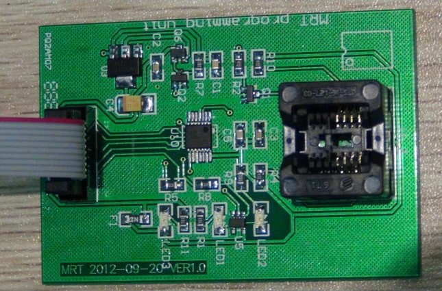
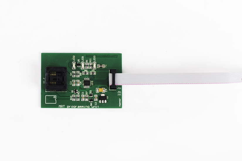
Attached photo of my programmer (V2)
@Michael Chiklis which version of programmer you have ? I tried again a lot of cycles read/write with a W25Q40BW and everything seems ok.
Attached photo of my programmer (V2)
- Attachments
-
Re: ST2000DM001 corrupt ROM
August 24th, 2015, 21:26
Version 1.0 of the programmer has an AMS1117-3.3 regulator and significantly different layout. It doesn't have the 14-pin chip at U2.
BTW, did you check the zero-ohm resistors near the 12V TVS diode?
BTW, did you check the zero-ohm resistors near the 12V TVS diode?
Re: ST2000DM001 corrupt ROM
August 24th, 2015, 21:57
fzabkar wrote:BTW, did you check the zero-ohm resistors near the 12V TVS diode?
Yes, and they are ok
Thanks
Re: ST2000DM001 corrupt ROM
August 26th, 2015, 10:27
I have this:
So probably your MRT external programmer can handle 1.8V ROMs
So probably your MRT external programmer can handle 1.8V ROMs
Re: ST2000DM001 corrupt ROM
August 26th, 2015, 17:55
michael chiklis wrote:So probably your MRT external programmer can handle 1.8V ROMs :wink:
AFAICS, there is nothing in the OP's photos that would confirm that. I would measure the Vcc pin to be certain. Otherwise, if the OP could let us know the markings on the chips, then perhaps we could work it out from the circuit.
BTW, MRT Lab's web site still shows version 1.0 of their programming unit.
http://en.mrtlab.com/wp-content/uploads ... mmer-1.jpg
http://en.mrtlab.com/mrt-pro
The MRT programmer reads and programs every ROM chip that complies with the SPI interface (e.g., the motherboard BIOS chip). By using the MRT programmer, the firmware can be brushed to either failed HDD ROM chips or damaged motherboard BIOS.
Powered by phpBB © phpBB Group.