SanDisk X300s Power issue?
February 16th, 2018, 8:59
Hi,
I got this Sandisk X300s 256GB drive that shows no sign of life hooking it up to the computer.
I've done some measurements. Perhaps someone (like fzabkar) could help checking if it looks correct?
Thanks!
I got this Sandisk X300s 256GB drive that shows no sign of life hooking it up to the computer.
I've done some measurements. Perhaps someone (like fzabkar) could help checking if it looks correct?
Thanks!
- Attachments
-
-
Re: SanDisk X300s Power issue?
February 16th, 2018, 9:02
Another closeup on the ICs.
- Attachments
-
Re: SanDisk X300s Power issue?
February 16th, 2018, 16:23
On this device, it’s much more likely that it’s suffering from firmware damage and/or flash degradation than an actual electronic fault.
Re: SanDisk X300s Power issue?
February 17th, 2018, 6:18
pcimage wrote:On this device, it’s much more likely that it’s suffering from firmware damage and/or flash degradation than an actual electronic fault.
Looks like you are correct.
It get BSY state as soon as its recieve any ATA command.
According to ACE, there is no solution for that issue yet.
Anyone who had success fixing this?
Re: SanDisk X300s Power issue?
February 17th, 2018, 17:15
Sorry for my late response. I've been trying to determine the identities and functions of many of the smaller ICs, without success. 
In any case ISTM that all the supplies are present (Vcore = 1V, 1.5V for SDRAM, 1.8V & 3.2V for NANDs). There are some voltages that don't make sense to me.
For example, the capacitor at the left edge of the PCB in "Foto 2018-02-16 13 23 41" has 0V across it.
The nearby T6 transistor has a collector voltage of 0V. ISTM that this transistor drives the enable pin of the dual converter (42H4 V087) on the other side of the PCB. I would have expected that 0V would disable the converter IC, but this is not the case.
Also, the PWDIS pin (SATA power P3) is sitting at 1.5V. AIUI, P3 enables/disables power to the board (just like DEVSLP in your M.2 thread), so it should be at 0V to enable power, and 3.3V to disable. Nevertheless, it appears that floating this pin is sufficient to enable the power, even if the voltage is low.
Power Disable Feature (SATA 3.2+ / 3.3):
http://www.hddoracle.com/viewtopic.php?f=42&t=2094
I have found some better photos in the following review:
SanDisk X300s 256GB review:
http://pc.zoznam.sk/sandisk-x300s-256gb-ssd-pre-firemne-prostredie?page=2
http://www.pretaktovanie.sk/obr/hdd/ssd/sandisk.sd7ub3q-256g/pcb-top-big.jpg
http://www.pretaktovanie.sk/obr/hdd/ssd/sandisk.sd7ub3q-256g/pcb-bottom-big.jpg
Marvell 88SS9188-BJM2, Marvell flash controller
15059 064G, SanDisk, 64Gb MLC NAND flash
D90NP, MT41K128M16JT-125 M:K, Micron, 2Gb (128Mb x 16), 1.35V, 800 MHz, CL11, DDR3L-RS SDRAM:
http://static6.arrow.com/aropdfconversion/3fa481f9b95270e81ded4ead384da91eb6589da8/pgurl_mt41k128m16jt-125.pdf
https://www.micron.com/~/media/documents/products/data-sheet/dram/ddr3/2gb_ddr3l-rs.pdf
TLV62090, Texas Instruments, 3A, 2.5V - 5.5V, Synchronous Step-Down Converter, marking SBV, 16-pin:
http://www.ti.com/lit/ds/symlink/tlv62090.pdf
DFLT6V0A, Diodes Inc, 6.0V, marking FAG, 225W, TVS diode:
http://www.diodes.com/_files/datasheets/ds30581.pdf
SMBJ6.0A, Diodes Inc, marking KG, unidirectionsl TVS diode, 600W:
https://www.diodes.com/assets/Datasheets/ds19002.pdf
https://www.diodes.com/assets/Datasheets/ds19003.pdf
GD25Q20C, GigaDevice, 2Mbit, 2.7V - 3.6V, serial flash memory:
http://www.gigadevice.com/product/download/146.html?locale=en_US
TPS22903, Texas Instruments, marking 4P, 3.6V, 0.5A, 68mOhm, Load Switch:
http://www.ti.com/lit/ds/symlink/tps22904.pdf
KGN, 6.0V unidirectionsl TVS diode
42H4 V087 = dual step-down buck converter
T6 = NPN transistor ?
N2 = zener diode ?
3XT 4-pin - load switch? - LDO?
U5A 4-pin - power supervisor ?
U2A 4-pin - power supervisor ?
HHR / HH7 -> HH - 6-pin ??
HS 6-pin ??
TV 6-pin ??
T7 4-pin - LDO?
T8 4-pin - 3.3V LDO?
CY - temperature sensor ? - similar to TMP100 and TMP101 ?
- Attachments
-
-
- TLV62090_pinout.gif (17.25 KiB) Viewed 25632 times
-
Re: SanDisk X300s Power issue?
February 18th, 2018, 9:24
Thanks for your input!
I've done some measurements. The pins 1,2 and 16 on the TVL62090 differs between the two components.
1 and 2 is the switch pins
16 is the output sense(?) pin
I've also grounded pin3, PWDIS, from the SATA Power but there is no difference.
I've done some measurements. The pins 1,2 and 16 on the TVL62090 differs between the two components.
1 and 2 is the switch pins
16 is the output sense(?) pin
I've also grounded pin3, PWDIS, from the SATA Power but there is no difference.
- Attachments
-
-
Re: SanDisk X300s Power issue?
February 18th, 2018, 14:21
fzabkar wrote:TPS22903, Texas Instruments, marking 4P, 3.6V, 0.5A, 68mOhm, Load Switch:
http://www.ti.com/lit/ds/symlink/tps22904.pdf
I might be blind, but which component is this?
Re: SanDisk X300s Power issue?
February 18th, 2018, 15:01
I doubt there is any hardware fault, but just to be sure ...
As expected, the TVL62090 voltages are correct. The differences reflect the different output voltages - one converter produces 1.0V, the other 3.3V.
The TPS22903 is that tiny component near the SATA connector.
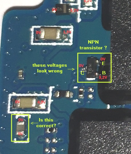
These voltages look wrong:
As expected, the TVL62090 voltages are correct. The differences reflect the different output voltages - one converter produces 1.0V, the other 3.3V.
The TPS22903 is that tiny component near the SATA connector.
- TPS22903.jpg (123.82 KiB) Viewed 25567 times
These voltages look wrong:
- enable_BJT.jpg (156.26 KiB) Viewed 25567 times
Re: SanDisk X300s Power issue?
February 18th, 2018, 16:26
fzabkar wrote:I doubt there is any hardware fault, but just to be sure ...
As expected, the TVL62090 voltages are correct. The differences reflect the different output voltages - one converter produces 1.0V, the other 3.3V.
The TPS22903 is that tiny component near the SATA connector.
These voltages look wrong:
The values are "correct". I double checked them again.
Even with Pin3 and Pin4 shorted on the SATA power cable.
The TPS22903 is to tiny! I need sharper probes
Re: SanDisk X300s Power issue?
February 18th, 2018, 17:07
Could you measure the voltages at the other "T6" component? Could you also test the B-E and B-C junctions on the diode range of your meter? Do they test like diodes?
Could you measure the resistance of the "0V capacitor"? Is it shorted?
- T6_volts.jpg (114.62 KiB) Viewed 25553 times
Could you measure the resistance of the "0V capacitor"? Is it shorted?
Re: SanDisk X300s Power issue?
February 19th, 2018, 4:24
fzabkar wrote:Could you measure the voltages at the other "T6" component? Could you also test the B-E and B-C junctions on the diode range of your meter? Do they test like diodes?
Could you measure the resistance of the "0V capacitor"? Is it shorted?
I managed to measure on that supersmall TPS2290, looks correct to me.
I added the T6 measurements on your image.
- Attachments
-
- T6_volts.jpg (69.88 KiB) Viewed 25501 times
-
- TPS2290.png (196.39 KiB) Viewed 25501 times
Re: SanDisk X300s Power issue?
February 19th, 2018, 17:25
I'm trying to determine whether T6 is an NPN BJT, or NPN digital transistor, or an n-channel enhancement mode FET. It's not testing like any of them. 
Can you measure the voltages at the circled test points in the previous image?
I'm also trying to determine whether the capacitor (?) at the bottom left corner of the next image is shorted. What is its resistance?
Can you measure the voltages at the circled test points in the previous image?
I'm also trying to determine whether the capacitor (?) at the bottom left corner of the next image is shorted. What is its resistance?
Re: SanDisk X300s Power issue?
February 20th, 2018, 5:16
fzabkar wrote:I'm trying to determine whether T6 is an NPN BJT, or NPN digital transistor, or an n-channel enhancement mode FET. It's not testing like any of them.
Can you measure the voltages at the circled test points in the previous image?
I'm also trying to determine whether the capacitor (?) at the bottom left corner of the next image is shorted. What is its resistance?
The resistance is about 330kOhm and 7.5uF
The other T6 has the following specs when doing the same diode measurements:
C-E = 0,5V
C-B = 1,88V
E-B = 1,88V
The voltage at those two circles are 3,3V each.
Re: SanDisk X300s Power issue?
February 20th, 2018, 15:58
Sorry, I can't identify T6. However, ISTM that it is doing its job which is to enable the adjacent regulator. I don't believe there is a hardware problem.
Re: SanDisk X300s Power issue?
February 20th, 2018, 16:25
fzabkar wrote:Sorry, I can't identify T6. However, ISTM that it is doing its job which is to enable the adjacent regulator. I don't believe there is a hardware problem.
Thanks for your effort!
I will see if I can find any info about why it’s ending up in the BSY-state.
Re: SanDisk X300s Power issue?
February 21st, 2018, 2:15
I have identified the "dual" buck regulator. It is in fact a triple buck regulator plus an LDO regulator.
LM10507, 3x Programmable Buck + 2.5V 250mA LDO Power Management IC (PMIC), marking V087, DSBGA (34):
http://www.ti.com/lit/ds/symlink/lm10507.pdf
Programmable Buck Regulators:
You may wish to retake your measurements around that area. ISTM that the +2.5V LDO supply is missing? I also cannot see the output of buck #2.
LM10507, 3x Programmable Buck + 2.5V 250mA LDO Power Management IC (PMIC), marking V087, DSBGA (34):
http://www.ti.com/lit/ds/symlink/lm10507.pdf
Programmable Buck Regulators:
- Buck #1: 0.9 - 3.4V; 1.6A
Buck #2: 0.9 - 3.4V; 1A
Buck #3: 0.865 - 1.5V; 1A
You may wish to retake your measurements around that area. ISTM that the +2.5V LDO supply is missing? I also cannot see the output of buck #2.
- Attachments
-
-
-
-
Re: SanDisk X300s Power issue?
February 21st, 2018, 2:30
The Marvell 88SS9188 is a dual-core flash controller. Shouldn't it have two Vcore supplies??? These would be around 1V.
Re: SanDisk X300s Power issue?
February 21st, 2018, 3:38
The T6 transistor appears to be controlling the PMIC's DEVSLP pin.
- Attachments
-
- DEVSLP_1.jpg (61.41 KiB) Viewed 25376 times
-
- DEVSLP_2.jpg (74.95 KiB) Viewed 25376 times
Re: SanDisk X300s Power issue?
February 21st, 2018, 14:57
You might be on to something with the LDO that is missing.
All the DEVSLP are set to 0V.
Buck #1 = 1.8V
Buck #3 = 1.5V
I will do some more measurements tomorrow, trying to locate where the LDO is beeing generated.
Edit: I missed that the LDO was an output, so it could be that the LM10507 itself is faulty?
All the DEVSLP are set to 0V.
Buck #1 = 1.8V
Buck #3 = 1.5V
I will do some more measurements tomorrow, trying to locate where the LDO is beeing generated.
Edit: I missed that the LDO was an output, so it could be that the LM10507 itself is faulty?
- Attachments
-
-
Re: SanDisk X300s Power issue?
February 21st, 2018, 15:56
AISI, the designer chose a PMIC with 3 buck regulators but only used 2 of them (buck #2 has no external components?). Seems like a strange choice to me.
I don't know whether the "0V capacitor" is filtering the LDO output (BGA makes it hard to see the connections), but ISTM that the capacitor must be there for a good reason. That said, the PMIC's regulators can be controlled by the flash controller via the SPI pins. Therefore, it could be that the LDO is being switched off by the firmware. In any case, I can't see where the +2.5V would be used.
Maybe I have introduced a red herring?
Powered by phpBB © phpBB Group.