Hitachi HDS722020ALA330 PCB SWAP support
November 11th, 2011, 8:50
Hi Everyone !
I have a problem with my hitachi drive which doesn't power on anymore (no spinning/vibration). One day I tried to plug it in my eSata dock without any result.
here are the informations written on the drive

HITACHI HDS722020ALA330 2TB SATA
Processor: LSI MUSE-B2B2-L 0A71261
P/N: 0F10311
MLC: JPK3EA
Firmware: 3EA
Date: APR-2010
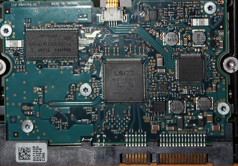
and here is a screen of the PCB

Number on the barcode :
0A71339
BA3293A
So I have another Hitachi HDS722020ALA330 which are currently working properly with close infos

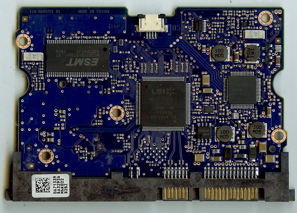
PCB screen
I have tried to swap the PCB board from my working disk to the patient and the HDD starts and spins again without stopping...
So I understood it was probably a PCB problem.
I put back the PCB on my (donor) working HDD which continue to work properly.
I realize after reading this forum this could damage the NVRAM and/or the preamp chips on both drives, is that right ? I do not understand clearly why ?)
Do you think it could have damage my patient HDD (my donor PCB seems to continue to works properly)
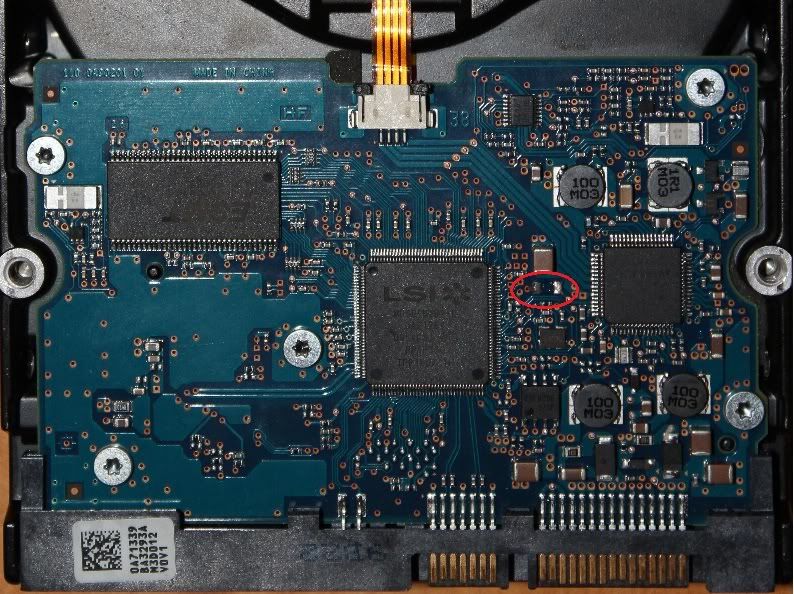
After I continue, and had a look on the wrong HDD and I noticed on the PCB that a component was missing or has been torn or unsoldered (surrounded in red)
it looks like a capacitor.
PATIENT PCB
DONOR PCB

In the meantime I have tried to find another Donor PCB closer than my failed HDD mainly with the same firmware version and same MLC and also because I don't want to sacrify my working PCB by swapping the NVRAM from the patient to the donor
I have found one (that I am waiting for)
New Donor PCB
HITACHI HDS722020ALA330 2TB SATA
Processor: LSI MUSE-B2B2-L 0A71261
P/N: 0F10311
MLC: JPK3EA
Firmware: 3EA
Date: JUL-2010
Number on the barcode :
0A71339
BA3293A
I have currently several questions :
- Is mandatory to move the NVRAM from the patient to the donor even if the parameters of these two drives are really close ? if yes can someone help me to
found it (I have surrounded in green what I thought the NVRAM)

- Would it be faster/easier to solder the missing capacitor on the non-working PCB ?
- I have read that another solution would be also to remove the TVS diodes on the board, one is 12VDC and the other 5VDC would it work in my case ?
If i have to move I will have to found someone to do that because I don't fell confortable
Thanks for your feedbacks
Diz
I have a problem with my hitachi drive which doesn't power on anymore (no spinning/vibration). One day I tried to plug it in my eSata dock without any result.
here are the informations written on the drive
HITACHI HDS722020ALA330 2TB SATA
Processor: LSI MUSE-B2B2-L 0A71261
P/N: 0F10311
MLC: JPK3EA
Firmware: 3EA
Date: APR-2010
and here is a screen of the PCB
Number on the barcode :
0A71339
BA3293A
So I have another Hitachi HDS722020ALA330 which are currently working properly with close infos
PCB screen
I have tried to swap the PCB board from my working disk to the patient and the HDD starts and spins again without stopping...
So I understood it was probably a PCB problem.
I put back the PCB on my (donor) working HDD which continue to work properly.
I realize after reading this forum this could damage the NVRAM and/or the preamp chips on both drives, is that right ? I do not understand clearly why ?)
Do you think it could have damage my patient HDD (my donor PCB seems to continue to works properly)
After I continue, and had a look on the wrong HDD and I noticed on the PCB that a component was missing or has been torn or unsoldered (surrounded in red)
it looks like a capacitor.
PATIENT PCB
DONOR PCB
In the meantime I have tried to find another Donor PCB closer than my failed HDD mainly with the same firmware version and same MLC and also because I don't want to sacrify my working PCB by swapping the NVRAM from the patient to the donor
I have found one (that I am waiting for)
New Donor PCB
HITACHI HDS722020ALA330 2TB SATA
Processor: LSI MUSE-B2B2-L 0A71261
P/N: 0F10311
MLC: JPK3EA
Firmware: 3EA
Date: JUL-2010
Number on the barcode :
0A71339
BA3293A
I have currently several questions :
- Is mandatory to move the NVRAM from the patient to the donor even if the parameters of these two drives are really close ? if yes can someone help me to
found it (I have surrounded in green what I thought the NVRAM)
- Would it be faster/easier to solder the missing capacitor on the non-working PCB ?
- I have read that another solution would be also to remove the TVS diodes on the board, one is 12VDC and the other 5VDC would it work in my case ?
If i have to move I will have to found someone to do that because I don't fell confortable
Thanks for your feedbacks
Diz
Re: Hitachi HDS722020ALA330 PCB SWAP support
November 12th, 2011, 15:31
Clearly you do have a PCB fault, and yes you do need to move the NVRAM (which you have correctly identified) to your donor PCB.
The reason is that this IC stores unique "adaptive" data. In particular it holds the location of the System Area which is different for each drive.
Here is an article that explains it in more detail:
http://www.datarecoverytools.co.uk/2009 ... am-repair/
Here is an explanation of the contents of NVRAM:
http://www.datarecoverytools.co.uk/2009 ... must-know/
http://www.salvationdata.com/blog/nvram-data-structure/
If you wish to test the TVS diodes, then get hold of a digital multimeter (US$5) and measure their resistances.
See http://www.users.on.net/~fzabkar/HDD/TVS_diode_FAQ.html
If you need help to move the NVRAM, then your local TV/AV reapir shop should be able to do it for you. Otherwise at least one person has reported that the following board supplier provide the service for US$20, even though the PCB was not purchased from him:
http://www.onepcbsolution.com/
Re: Hitachi HDS722020ALA330 PCB SWAP support
November 16th, 2011, 15:29
Hi Everyone !
Just to let you know that after the PCB swap and the NVRAM move from the patient to the donor my 2 To HDD is back to life

I am pretty happy this evening !
I would like to truly thanks all people here on this board who share their knowledge and give good advices ...
Honesty 2 weeks ago I was almost pretty sure the HDD was dead so ...
One more time thank you very much to all involved on this forum ! keep going ...
Diz
Just to let you know that after the PCB swap and the NVRAM move from the patient to the donor my 2 To HDD is back to life
I am pretty happy this evening !
I would like to truly thanks all people here on this board who share their knowledge and give good advices ...
Honesty 2 weeks ago I was almost pretty sure the HDD was dead so ...
One more time thank you very much to all involved on this forum ! keep going ...
Diz
Re: Hitachi HDS722020ALA330 PCB SWAP support
January 8th, 2012, 18:23
Hi, I am also having an issue with a Hitachi 2tb drive - attempted to attach it and one of the components started smoking - I did notice that it didn't spin at all during the brief application of power. Any idea on where to obtain a replacement PCB? I will attempt to attach the pics
- Attachments
-
- PCB
-
- cover label
Re: Hitachi HDS722020ALA330 PCB SWAP support
January 8th, 2012, 18:32
dizmo, dizmo, HI, where were you able to obtain replacement PCB's for the hard drive? My drive is same as yours, the info is 0A71339 BA3293A - desperately trying to get so I can spin the drive and recover files.
Thanks
Thanks
Re: Hitachi HDS722020ALA330 PCB SWAP support
January 8th, 2012, 22:11
Post in the hard drive market section of the forum.
You can also try eBay.
You can also try eBay.
Re: Hitachi HDS722020ALA330 PCB SWAP support
May 24th, 2012, 10:55
Hi,
My drive just stopped working for no reason, and it is the same type, with the same data "APR-2010".
Mine doesn't have that little component missing that yours did. Nothing looks blown or anything, it just doesn't power on or spin up.
It is still under Hitachi Warranty until APR 2013. I can submit an RMA on their website, but they just want me to send the drive, and they will send me a replacement.
But wouldn't it be easier for them to just replace the PCB and NVRAM like you did, so I don't lose all my data?
I have emailed support, so I will see what they say. I won't hold my breath.
I just wanted to stop by and say thanks for all the photos and information
Cheers,
ValTrum.
Re: Hitachi HDS722020ALA330 PCB SWAP support
May 24th, 2012, 15:36
valtrum wrote:Hi,
But wouldn't it be easier for them to just replace the PCB and NVRAM like you did, so I don't lose all my data?
Cheers,
ValTrum.
That sort of involves work - using resources (human or machine capable of doing the job correctly, plus equipment, plus parts, which themselves have to be compatible and the space these would oocupy - which would drive their cost up as probably dozens and dozens of drives fail everyday.
Much cheaper to just replace the drive.
Re: Hitachi HDS722020ALA330 PCB SWAP support
May 25th, 2012, 0:58
valtrum wrote:But wouldn't it be easier for them to just replace the PCB and NVRAM like you did, so I don't lose all my data?
IMHO, the HDD manufacturers could maintain a database of NVRAM images (they are a storage company after all). Then, when a customer requests a replacement PCB, the manufacturer could look up the serial number and program a replacement board for him.
Re: Hitachi HDS722020ALA330 PCB SWAP support
May 27th, 2012, 12:50
fzabkar wrote:valtrum wrote:But wouldn't it be easier for them to just replace the PCB and NVRAM like you did, so I don't lose all my data?
IMHO, the HDD manufacturers could maintain a database of NVRAM images (they are a storage company after all). Then, when a customer requests a replacement PCB, the manufacturer could look up the serial number and program a replacement board for him.
In an ideal world yes but thats never going to happen
Re: Hitachi HDS722020ALA330 PCB SWAP support
June 4th, 2012, 6:10
Hi Everyone... I am new to this forum, was searching for fried External Hard drive & saw this thread... I have Merlin Ent. External 2 Tb Hard drive, I backed up my office work on it & formatted my office laptop & when I tried connecting this drive a message came up saying this drive not formatted & requires format so I thought I take the hard drive out & connect it using cables I have & fried my drive.....  & now I am stuck where to get a software for my office work retrive and I saw this thread for changing pcb is it possible cuz I saw people saying this is not possible now days.... Pls help... Many Thanks
KP
KP
Re: Hitachi HDS722020ALA330 PCB SWAP support
June 4th, 2012, 19:28
The OP above did it, so it is possible.
Re: Hitachi HDS722020ALA330 PCB SWAP support
June 6th, 2012, 1:09
KPDesigners wrote:so I thought I take the hard drive out & connect it using cables I have & fried my drive...
Can you see any damaged components?
Powered by phpBB © phpBB Group.