ST4000NM0165 ROM problem
August 11th, 2025, 11:27
Hi everyone,
I got a ST4000NM0165 HP branded (Makara Plus) with a defective board.
I found same PCB code 100760706 on ST4000NM0035 ( Seagate branded ). I tried to swap the ROM chip, but the drive shows LED:0x000000BB and no spin on.
I tried to load original board firmware and import adaptives from customer ROM, drives spins but shows Disc FW failed to load error.
I have no error in the log of PC3K when I load the rom file, so I assume that the ROM file is not corrupted. I also tried to open the ROM with F3RomExplorer and seems to be good
Do you have some suggestions?
Thanks a lot
Re: ST4000NM0165 ROM problem
August 11th, 2025, 20:55
get terminal access to help diagnose.
Re: ST4000NM0165 ROM problem
August 12th, 2025, 11:20
Unfortunately no way to terminal access. I just have a partial terminal access after hotswap and loaded adaptives in RAM, but first command I get LED error.
Re: ST4000NM0165 ROM problem
August 12th, 2025, 14:32
"LED:0x000000BB" - Try importing the donor log segment into the original ROM.
"Disc FW failed to load error" - maybe the preamp or heads are bad?
"Disc FW failed to load error" - maybe the preamp or heads are bad?
Re: ST4000NM0165 ROM problem
August 12th, 2025, 17:34
Can you upload patient and donor ROMs?
Re: ST4000NM0165 ROM problem
August 13th, 2025, 3:38
fzabkar wrote:Can you upload patient and donor ROMs?
Sure, ROMs attached.
Thanks
- Attachments
-
- donor.7z
- (340.51 KiB) Downloaded 40 times
-
- patient.7z
- (346.92 KiB) Downloaded 41 times
Re: ST4000NM0165 ROM problem
August 13th, 2025, 9:41
Patient+CELogDonor:
- Attachments
-
- Patient_CELogDonor.zip
- (442.18 KiB) Downloaded 39 times
Re: ST4000NM0165 ROM problem
August 13th, 2025, 9:56
SWM wrote:Patient+CELogDonor:
Hi,
Thanks for your reply, but still Same error and no spin on.
Boot0x80MBW0E61HPS1
LED:0x000000BB FAddr:0x00009039
Re: ST4000NM0165 ROM problem
August 13th, 2025, 15:05
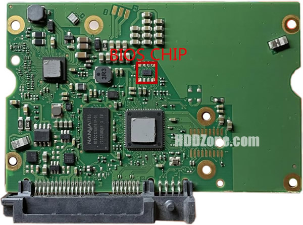
Your PCB has two e-fuses. Can you upload a photo? If the fault is confined to these fuses, the repair should cost you nothing.
https://www.hddzone.com/images/100760706.jpg
https://www.hddzone.com/images/100760706.jpg
Re: ST4000NM0165 ROM problem
August 14th, 2025, 5:14
fzabkar wrote:Your PCB has two e-fuses. Can you upload a photo? If the fault is confined to these fuses, the repair should cost you nothing.
https://www.hddzone.com/images/100760706.jpg
This is my PCB:
Thanks
- Attachments
-
Re: ST4000NM0165 ROM problem
August 14th, 2025, 6:24
MP5000S, Monolithic Power, 12V, 1A - 5A Programmable Current Limit Switch, marking ADT, QFN10:
https://www.monolithicpower.com/en/documentview/productdocument/index/version/2/document_type/Datasheet/lang/en/sku/MP5000S/document_id/1651/
MP5010S, Monolithic Power, 5V, 1A - 5A Programmable Current Limit Switch, marking AGK, QFN10:
https://www.monolithicpower.com/en/documentview/productdocument/index/version/2/document_type/Datasheet/lang/en/sku/MP5010S/document_id/1673/
Measure the input and output voltages of each device.
- Attachments
-
Re: ST4000NM0165 ROM problem
August 14th, 2025, 7:16
Here the results..
- Attachments
-
Re: ST4000NM0165 ROM problem
August 14th, 2025, 13:37
Are the outputs shorted to ground?
Are the 3.3V SATA power pins all at 0V?
Are the Enable pins of each fuse at a high logic level?
Are the 3.3V SATA power pins all at 0V?
Are the Enable pins of each fuse at a high logic level?
Re: ST4000NM0165 ROM problem
August 14th, 2025, 15:23
It would be interesting to know: does the RAM size on the boards match? This is not urgent. Thanks. 
Re: ST4000NM0165 ROM problem
August 18th, 2025, 7:07
fzabkar wrote:Are the outputs shorted to ground?
Are the 3.3V SATA power pins all at 0V?
Are the Enable pins of each fuse at a high logic level?
Hi,
here the results:
Are the outputs shorted to ground? NO
Are the 3.3V SATA power pins all at 0V? Yes, all 3.3V sata power pins are to 0V
Are the Enable pins of each fuse at a high logic level? Not at all. I have 1,3V on EN pins of both devices
SWM wrote:It would be interesting to know: does the RAM size on the boards match? This is not urgent. Thanks.
Effectively RAM seems to be different W631GG6KB vs W632GG6MB.
Could it be the reason that the ROM file is not compatible?
Thanks
Re: ST4000NM0165 ROM problem
August 18th, 2025, 8:58
n3dv3d wrote:Effectively RAM seems to be different W631GG6KB vs W632GG6MB.
Could it be the reason that the ROM file is not compatible?
If the ROM was re-installed from 2 Mbit to 1 Mbit - most likely bb.
Vice versa - there may also be nuances in the GPIO.
The EN of the fuses is from 2.5 to 5V. I would try to supply from 5V through a 100-200 Ohm resistor to 3.3V. Or put 0 Ohm resistors in the designated places. But here fzabkar will figure it out better.
Perhaps, when you solve the power problem, the patient's board will work.
Re: ST4000NM0165 ROM problem
August 18th, 2025, 11:39
https://www.mouser.com/datasheet/2/949/w631gg6kb_a10-2525588.pdf (W631GG6KB, 8M x 8 BANKS x 16 BIT DDR3 SDRAM, 1Gbit)
https://pf.unikeyic.com/datasheet/4c/99/79a3/35/76fa3bb40b98e7c58dc0bccc21ac3995.pdf (W632GG6MB, 16M x 8 BANKS x 16 BIT DDR3 SDRAM, 2Gbit)
The Enable/Fault pin appears to be in a fault state.
ISTM that both e-fuses have latched off. The only component that is connected to both the 5V and the 12V supplies is the motor controller.
https://pf.unikeyic.com/datasheet/4c/99/79a3/35/76fa3bb40b98e7c58dc0bccc21ac3995.pdf (W632GG6MB, 16M x 8 BANKS x 16 BIT DDR3 SDRAM, 2Gbit)
The Enable/Fault pin appears to be in a fault state.
- Code:
Intermediate Level Input Voltage VI (INT) -- Thermal Fault, Output Disabled -- 0.82V (min) 1.4V (typ) 1.95V (max)
The Enable/Fault pin is a tri-state, bi-directional interface. It can be used to enable the output of the device by floating the pin, or disable the chip by pulling it to ground (using an open drain or open collector device). If a thermal fault occurs, the voltage on this pin will go to an intermediate state to signal a monitoring circuit that the device is in thermal shutdown.
Thermal protection
When thermal protection is triggered, the output is disabled and the fault line is driven to the middle level. The thermal fault condition is latched, and the part will remain latch off state until restart the power or reset the enable pin.
Enable / Fault Pin
The Enable/Fault Pin is a Bi-Directional three levels I/O with a weak pull up current (28uA typical). The three levels are low, mid and high. It functions to enable/disable the part and to relay Fault information.
Enable/Fault pin as an input:
1. Low and mid disable the part.
2. Low, in addition to disabling the part, clears the fault flag.
3. High enables the part (if the fault flag is clear).
Enable/Fault pin as an output:
1. The pull up current may (if not over ridden) allow a “wired nor” pull up to enable the part.
2. An under voltage will cause a low on the Enable/Fault pin, and will clear the fault flag.
3. A thermal fault will cause a mid level on the Enable/Fault pin, and will set the fault flag.
ISTM that both e-fuses have latched off. The only component that is connected to both the 5V and the 12V supplies is the motor controller.
Re: ST4000NM0165 ROM problem
August 18th, 2025, 15:42
Before bypassing the e-fuses, you might like to test the resistances between ground and each of the voltage test points. I haven't labelled many of them because I don't know their function.
Si1413DH, Vishay, MOSFET, P-ch, -20V, -2.3A, 1.8V rated, marking BCxxy, SOT-363:
https://www.vishay.com/doc?71878
W25Q16JWBYIM, Winbond, 16Mbit serial flash, 1.8V, Quad SPI, marking 4Ayw + JIM, WLCSP-8:
https://www.mouser.com/datasheet/2/949/W25Q16JW_RevD_01152020_Plus-1760324.pdf
LX7178-01CSP, Microsemi, Constant Frequency Hysteretic Synchronous Buck Regulator with I2C, 3V - 5.5Vin, 5A, 1.875 MHz, marking 7801, WLCSP-20:
https://ww1.microchip.com/downloads/en/DeviceDoc/lx7178_rev1.1.pdf
- Attachments
-
-
-
-
Re: ST4000NM0165 ROM problem
August 19th, 2025, 5:22
Hi, thanks a lot for your reply.
Below the results.
I noticed the backup caps start at 3,2V then discharge to 0. In the working PCB stay fixed to 12V.
Below the results.
I noticed the backup caps start at 3,2V then discharge to 0. In the working PCB stay fixed to 12V.
- Attachments
-
-
-
-
Re: ST4000NM0165 ROM problem
August 19th, 2025, 6:26
I didn't expect that you would find any voltages. Instead, I was expecting you to measure resistances.
Both e-fuses have latched into a fault state and switched off their outputs. This suggests that there are shorts downstream. There appear to be two MOSFETs between the e-fuses and the motor controller, so I was wondering if there was a short after the MOSFETs.
Both e-fuses have latched into a fault state and switched off their outputs. This suggests that there are shorts downstream. There appear to be two MOSFETs between the e-fuses and the motor controller, so I was wondering if there was a short after the MOSFETs.
Powered by phpBB © phpBB Group.