Repair Hitachi pcb
April 19th, 2007, 13:41
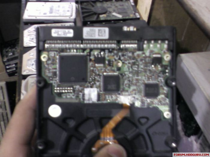
I need to repair pcb which is of a hitachi drive and i have attached the picture below can someone tell me what is the problem in most of the cases when there is no power in hdd . Like which of the components are bad .
Thanks .
Thanks .
April 22nd, 2007, 9:35
Rameez check your MSN I sent you the schematic.
i think best thing is tracing
April 22nd, 2007, 12:02
salam alekm
i thisnk best thing in this cas is tracing 5 and 12 volt to see where it disappear in the pcb
i thisnk best thing in this cas is tracing 5 and 12 volt to see where it disappear in the pcb
April 24th, 2007, 2:35
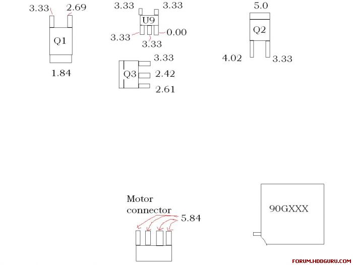
thanks for reply but tracing the voltage seems to be a very time taking process . Like in maxtor drives there are two points where u can measure the
3.3v and 5v if there is any problem with that u can change the component corresponding to it , is there any point on IBM like this .
3.3v and 5v if there is any problem with that u can change the component corresponding to it , is there any point on IBM like this .
i need to know where these 2 points in maxtor
April 24th, 2007, 9:31
salam alekm
i need to know where these 2 points in maxtor
i need to know where these 2 points in maxtor
April 24th, 2007, 9:37
Heres the main voltages on a working IC35L040AVER07-0. Seems to have same PCB. Try cold spray, or fingers to see if 90G2018 gets warm or hot, and check voltages with the pinout I PM'd you. If 90G gets warm for a few seconds, then goes cold it's probably the problem. You should feel Q1, Q2, & Q3 get warm but not hot. If they stay cold check the voltage at pins also.
thanks too much on hitachi pcb but i want maxtor 6y80l0 pcb
April 24th, 2007, 10:14
salam alekm
i want maxtor pcb main faults please
i want maxtor pcb main faults please
April 24th, 2007, 15:57
These are the two points :

April 24th, 2007, 15:58
if any one has any other useful info please share .
Thanks .
Thanks .
and how to repair these errors in these points?
April 27th, 2007, 12:04
salam alekm
and how to repair these errors in these points?
and how to repair these errors in these points?
April 28th, 2007, 3:47
Hello,
first: the 5V test point shown on the picture is -5V in reality. Not that much of a difference
3.3V: if not present, probably the L7250E motor combo is damaged, but there is also a fusing resistor near R504 (on calypso III boards), this can be broken too, but mostly it is broken only after a power surge on the 5V line. Can be caused by the transistor (Q501) damage too, but I have never seen such case.
-5V: if not present, the L7250E or the FDFS2P102 (W503 on some boards) can be burnt. But be careful, if it is burnt there should be a cause for that, for example a preamp damage inside the HDA.
BTW I am always telling anybody who wants to touch a PCB should have at least some basic education of electronics, preferably an experienced technician or engineer...
Just to recognize the parts and figure out their function at least.
regards,
pepe
April 29th, 2007, 15:51
Shortscurcuits wrote:Rameez check your MSN I sent you the schematic.
I'm working on the same problem like Rameez. I have a broken HDS722516VLAT80, where the electronic seams to be broken. Here the schematic would be usefull. This shematics will also be usefull, if I it is not the same type, so I can go one with the pionouts.
Thank's a lot for each help and effort.
AVILA
May 2nd, 2007, 1:15
Hi Avila I don't have the schematic for the IBM boards. If anyone has the datasheet for 90G2018 chip, I would appreciate it. I checked the Hitatchi site but it is no longer there for the partners program.
Powered by phpBB © phpBB Group.