Re: seagate 2GB st2000dm001 dead
August 12th, 2014, 15:30
michael chiklis wrote:If your rom chip is also burnt then no one can help you
NOT TRUE, but expensive AND there are some "IF" and limits (however with great % of successful recover of data).
Re: seagate 2GB st2000dm001 dead
August 12th, 2014, 21:15
BlackST wrote:michael chiklis wrote:If your rom chip is also burnt then no one can help you
NOT TRUE, but expensive AND there are some "IF" and limits (however with great % of successful recover of data).
That's what i meant in the P.S. that you haven't quoted.
P.S.
I know only one guy in this forum that maybe is able to rebuild rom if chip is burnt, he is "dmarques" (in Portugal) but this job is very expensive!
Maybe you can explain us this "IF" and limits, it would be much interesting response
but all we know that you don't explain it...
Re: seagate 2GB st2000dm001 dead
August 13th, 2014, 2:39
If you were a customer asking me to recover F3s without Rom, given the original hdd, you would know the ifs and limits at diagnose stage.
I don't know how other people work, only my stuff.
At present, some models are still problematic and each case is considered unique.
I don't know how other people work, only my stuff.
At present, some models are still problematic and each case is considered unique.
Re: seagate 2GB st2000dm001 dead
August 13th, 2014, 6:47
anelito wrote:hhddrec wrote:Note:
In case of 1 pin broken maybe reparable
How I could repare the pin broken?
thanks
Broken Pin is reparable; but skills with Iron needed, hard job
Re: seagate 2GB st2000dm001 dead
August 13th, 2014, 9:50
No need to repair pin, i have a trick 
Re: seagate 2GB st2000dm001 dead
August 13th, 2014, 9:58
michael chiklis wrote:No need to repair pin, i have a trick
what trick?
Re: seagate 2GB st2000dm001 dead
August 13th, 2014, 16:06
Google turns up thousands of hits on the subject. It seems that the obvious solution works for most people, namely to use a dremel or knife to scrape away enough of the plastic package to expose the stub of the pin.
http://www.google.com/search?q=%22broke ... +IC+repair
http://www.google.com/search?q=%22broke ... +IC+repair
Re: seagate 2GB st2000dm001 dead
August 13th, 2014, 18:26
My trick is to use SOP8 to DIP8 adapter as this:
https://www.google.it/search?q=SOP8+To+ ... d=0CC8QsAQ
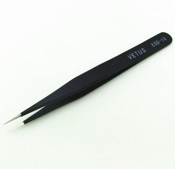
i insert the rom chip in the adapter, all rom pins will be connected to the adapter pins except the one that is broken, then i use thin tweezers with metal tips:
http://www.drivestar.biz/images/univers ... esd-10.jpg
with one of the tweezers tips keep touching rom stub pin and the adapter pin together to ensure electrical connection, then read rom with eprom programmer.
I read rom many times, 10 times for example, and save all on 10 files.
Then i compare all those files with Hex editor such as Hex Workshop to find if saved files are all same, if two or more are the same then means that very likely is a good rom read.
Hex comparing is needed because connection with tip twezeers is not perfect (you might have bad readings), you have to keep a steady hand while you read the rom.
After all you can write the good rom reading into a new rom chip by using the eprom.
https://www.google.it/search?q=SOP8+To+ ... d=0CC8QsAQ
i insert the rom chip in the adapter, all rom pins will be connected to the adapter pins except the one that is broken, then i use thin tweezers with metal tips:
http://www.drivestar.biz/images/univers ... esd-10.jpg
with one of the tweezers tips keep touching rom stub pin and the adapter pin together to ensure electrical connection, then read rom with eprom programmer.
I read rom many times, 10 times for example, and save all on 10 files.
Then i compare all those files with Hex editor such as Hex Workshop to find if saved files are all same, if two or more are the same then means that very likely is a good rom read.
Hex comparing is needed because connection with tip twezeers is not perfect (you might have bad readings), you have to keep a steady hand while you read the rom.
After all you can write the good rom reading into a new rom chip by using the eprom.
Re: seagate 2GB st2000dm001 dead
August 14th, 2014, 14:59
the measurements of my rom bios chip is:
voltage vs ground:
1 1.76 V
2 0.02 V possible dead
3 1.79
4 0 (ground)
5 0.002 possible dead
6 1.8
7 1.8
8 1.8
pins 2 and 5 are the input output pins.
what shoul I do?
thanks
voltage vs ground:
1 1.76 V
2 0.02 V possible dead
3 1.79
4 0 (ground)
5 0.002 possible dead
6 1.8
7 1.8
8 1.8
pins 2 and 5 are the input output pins.
what shoul I do?
thanks
Re: seagate 2GB st2000dm001 dead
August 14th, 2014, 15:57
The problem seems to be within the chip. not that the pin is split. someone has the block diagram of my rom bios chip?
my rom bios chip is Winbond W25Q40BW.
thanks
my rom bios chip is Winbond W25Q40BW.
thanks
Re: seagate 2GB st2000dm001 dead
August 14th, 2014, 16:08
pin 1 - 1,8V means chip is not used now (chip select dissabled)
pin 2 - Data Out, High impedance state, because chip select is high
pin 3 - /Write protect - High ? (disabled ?) weird...
pin 5 - Data In, 0V, chip select is high, nothing to transfer...
pin 6 - High ? It probably uses SPI mode 1,1
pin 7 - /HOLD - High = not in HOLD mode
pin 8 - Vdd
Flash chip is simply not used while you measure it (pin 1 high). Pin voltages seem fine, no overvoltages, but this actually says nothing ... you need to connect it to EEPROM programmer. Easiest solution to check Flash chip (if you are skilled with MCUs) is programming PIC or Atmega (any microcontroller with SPI) to read it (if it works), but you need knowledge and experiences to do that, or as i said, use compatible EEPROM programmer.
Re: seagate 2GB st2000dm001 dead
August 14th, 2014, 16:27
http://www.nexflash.com/NR/rdonlyres/6B ... 5Q40BW.pdf
Datasheet, google first link ...
Datasheet, google first link ...
Re: seagate 2GB st2000dm001 dead
August 14th, 2014, 16:47
Jano952 wrote:http://www.nexflash.com/NR/rdonlyres/6BF45188-BD1F-4F85-B352-171B5CB387C7/0/W25Q40BW.pdf
Datasheet, google first link ...
yes, I read it before, but the block diagram is not the electrical block diagram.
if my pin voltages seem fine, where is the problem? what is the problem?
what should I do?
thanks
Re: seagate 2GB st2000dm001 dead
August 14th, 2014, 16:56
@anelito, did you measure the zero-ohm resistors? These normally go open circuit, like fuses.
http://www.users.on.net/~fzabkar/HDD/ST ... 01_TVS.jpg
I can see that your "specialized service" people removed the 5V TVS diode, but it appears that they did not check the associated resistors. Normally the DIY solution is to remove the diode and flow a blob of solder over each of these resistors. There is a slight risk that the preamp may have been damaged (because it is powered from the +5V supply), but my experience from watching the storage forums is that DIY-ers are usually successful.
Re: seagate 2GB st2000dm001 dead
August 14th, 2014, 17:07
yes fzabkar, the tech service measured it. then, they removed the 5V TVS diode testing the PCB.
now my rom bios is in a new donor PCB without problem.
now my rom bios is in a new donor PCB without problem.
Re: seagate 2GB st2000dm001 dead
August 14th, 2014, 17:08
But he said that Flash IC has 1.8V supply and this voltage is converted from 5V supply, so they must be fine .
EDIT: I saw your last post too late
Well, your only chance is to desolder it (maybe it will work in PCB too) and check it in EEPROM programmer. Testing in different PCBs wont help. They said there is no current going into PCB, but that is impossible , Did they check voltages on coils ? Pro DRs should also use logic analyzers to check output from Flash ROM.
EDIT: I saw your last post too late
Well, your only chance is to desolder it (maybe it will work in PCB too) and check it in EEPROM programmer. Testing in different PCBs wont help. They said there is no current going into PCB, but that is impossible
Re: seagate 2GB st2000dm001 dead
August 18th, 2014, 19:25
my eeprom seems works well, so,
where is the problem? what is the problem?
can I do another test to the disc?
thanks
where is the problem? what is the problem?
can I do another test to the disc?
thanks
Re: seagate 2GB st2000dm001 dead
August 18th, 2014, 19:45
My approach is always to determine the nature of the original fault. Then proceed from there.
To this end, I would take the original PCB, without its EEPROM, and measure its supply voltages.
To this end, I would take the original PCB, without its EEPROM, and measure its supply voltages.
- Attachments
-
- ST2000DM001_regs_2.jpg (163.31 KiB) Viewed 14638 times
-
- unknown.jpg (55.6 KiB) Viewed 14638 times
Re: seagate 2GB st2000dm001 dead
August 18th, 2014, 19:58
Ok, after I send you the original PCB voltages.
also, may I perform some tests to rule out that the problem is the arm or discs?
thanks
also, may I perform some tests to rule out that the problem is the arm or discs?
thanks
Re: seagate 2GB st2000dm001 dead
August 18th, 2014, 20:02
I can't help with internal faults, but a serial terminal log may at least allow others to see the problem.
Powered by phpBB © phpBB Group.