Re: ST3000DM001 - 9YN166 Drive not detect, Spin Up, 11Click'
September 20th, 2014, 17:36
Unfortunately, maybe you're right that my programmer does not work with low voltage IC's, because I've tried everything and do not Detect ID, manufacturer, and even more content. I have SPI flash programmer: http://tehnikservice.net/blog/wp-conten ... -proto.jpg , willem also capitulated, with this IC's 

Re: ST3000DM001 - 9YN166 Drive not detect, Spin Up, 11Click'
September 20th, 2014, 17:40
What are the markings on IC1, IC2, and IC3?
IC2 and IC3 look like linear regulators.
Edit: I found it:
http://tehnikservice.net/projects/spi-f ... mmer-v2-2/
It handles 5V and 3.3V devices only.
IC2 and IC3 look like linear regulators.
Edit: I found it:
http://tehnikservice.net/projects/spi-f ... mmer-v2-2/
It handles 5V and 3.3V devices only.
Re: ST3000DM001 - 9YN166 Drive not detect, Spin Up, 11Click'
September 20th, 2014, 17:44
IC1 - 74HC244 IC2 - 7805, IC3 - 1117 - 3,3V. 3.3V section has been adapted to 2V, nothing was change.
Re: ST3000DM001 - 9YN166 Drive not detect, Spin Up, 11Click'
September 20th, 2014, 18:25
I expect that the parallel port might not function reliably at 2V signal levels.
Re: ST3000DM001 - 9YN166 Drive not detect, Spin Up, 11Click'
September 21st, 2014, 18:47
Ok, so what do you recommend programmer for the IC's, which you can build !?
PS. I tried even combined with my programmers, but to no avail.
PS, Pre stinks of to me here Bad adaptive heads in ROM or harmful changes FW CC4B on your CC4H. Sorry for my english
 Data is not importand, because, disc is empty.
PS. I tried even combined with my programmers, but to no avail.
PS, Pre stinks of to me here Bad adaptive heads in ROM or harmful changes FW CC4B on your CC4H. Sorry for my english
Data is not importand, because, disc is empty.
Re: ST3000DM001 - 9YN166 Drive not detect, Spin Up, 11Click'
September 21st, 2014, 19:57
I would purchase a USB-LVTTL adapter based on the CP2104 bridge or perhaps the "D" version of the PL-2303HX controller. You will probably find that the standard offerings only support 3.3V supplies, but it would be very simple to modify them for 1.8V and 2.5V using fixed or adjustable LDO regulators (eg LD1117-18).
See http://http://www.alexsoft.org/viewtopi ... 192&p=1779
For example, a typical CP2104 design would connect the VDD output from the IC's internal 3.3V regulator to the IC's VIO input. To modify this design for 1.8V I/O, you would cut this VDD-VIO connection and wire the output of your external LDO regulator to the VIO pin.
Alternatively, see the level shifter in the following thread:
viewtopic.php?f=1&t=29286
It works by converting a 0V-1.8V output range from the HDD to a 0.6V-2.4V input range for the bridge.
See http://http://www.alexsoft.org/viewtopi ... 192&p=1779
For example, a typical CP2104 design would connect the VDD output from the IC's internal 3.3V regulator to the IC's VIO input. To modify this design for 1.8V I/O, you would cut this VDD-VIO connection and wire the output of your external LDO regulator to the VIO pin.
Alternatively, see the level shifter in the following thread:
viewtopic.php?f=1&t=29286
It works by converting a 0V-1.8V output range from the HDD to a 0.6V-2.4V input range for the bridge.
Re: ST3000DM001 - 9YN166 Drive not detect, Spin Up, 11Click'
September 22nd, 2014, 1:29
fzabkar wrote:I would purchase a USB-LVTTL adapter based on the CP2104 bridge or perhaps the "D" version of the PL-2303HX controller. You will probably find that the standard offerings only support 3.3V supplies, but it would be very simple to modify them for 1.8V and 2.5V using fixed or adjustable LDO regulators (eg LD1117-18).
See http://http://www.alexsoft.org/viewtopi ... 192&p=1779
For example, a typical CP2104 design would connect the VDD output from the IC's internal 3.3V regulator to the IC's VIO input. To modify this design for 1.8V I/O, you would cut this VDD-VIO connection and wire the output of your external LDO regulator to the VIO pin.
Alternatively, see the level shifter in the following thread:
viewtopic.php?f=1&t=29286
It works by converting a 0V-1.8V output range from the HDD to a 0.6V-2.4V input range for the bridge.
Sorry, brain fart. I replied to the wrong post. Please ignore.
Re: ST3000DM001 - 9YN166 Drive not detect, Spin Up, 11Click'
September 22nd, 2014, 12:26
Hehe, Ok frank. So what we do!? I think my problem is to solve and how you charge ROM, which is LE25FS40 maybe something more to say?
Re: ST3000DM001 - 9YN166 Drive not detect, Spin Up, 11Click'
September 22nd, 2014, 16:54
I have seen a 1.8V adapter for a Willem II programmer, but it looks like a kludge to me. Basically it reduces the IC's supply voltage by 2 diode drops, ie Vcc - 1.2V. IIUC, the programmer's Vcc is 3.6V, so this means the IC's Vcc becomes 2.4V. Three diodes would reduce the supply to 1.8V. Perhaps you could modify your own circuit by powering the 74HC244 from 3.3V, and then reducing this supply with 2 diodes to power the SPI flash (3.3 - 2 x 0.6 = 2.1V). You would still need the clamp diodes (D4, D5, D6) on the IC's input pins (/CS, SCK, SI).
http://www.ezoflash.com/downloads/ser_b1.zip
http://www.ezoflash.com/adapters.htm
http://www.ezoflash.com/chip_database.p ... ip=EN25S40
http://www.ezoflash.com/downloads/ser_b1.zip
http://www.ezoflash.com/adapters.htm
http://www.ezoflash.com/chip_database.p ... ip=EN25S40
Re: ST3000DM001 - 9YN166 Drive not detect, Spin Up, 11Click'
September 24th, 2014, 5:40
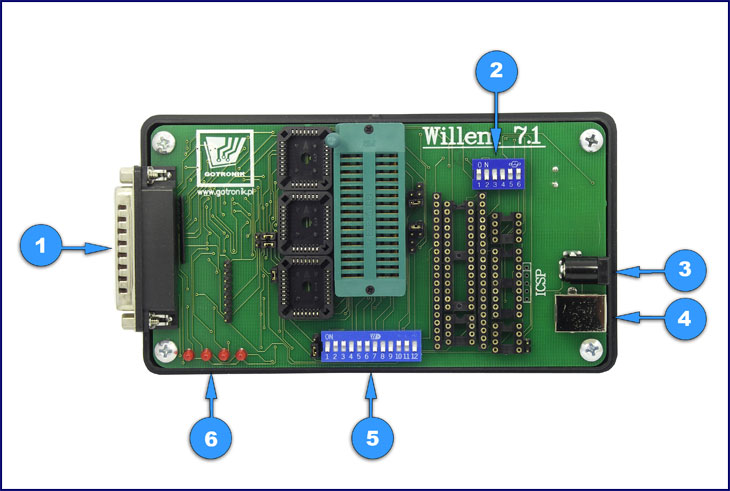
Ok, Is this programmer http://www.gotronik.pl/img/willem7_1_1.jpg with this adapter can operate? Do I have to build the entire Willem EZOFlash !?
Re: ST3000DM001 - 9YN166 Drive not detect, Spin Up, 11Click'
September 24th, 2014, 16:55
Sorry, I can't answer your question.
If I were buying a programmer, I would choose one that was specifically designed with 1.8V devices in mind. The Willem programmers appear to have been configured for a Vcc of 3.6V. The Willem/EZOFlash 1.8V adapters are a "kludge", IMHO.
AFAICT, the REVELPROG-IS looks promising, but it costs around US$130:
http://www.reveltronics.com/en/products ... rammer-usb
It appears to be versatile and well supported.
If I were buying a programmer, I would choose one that was specifically designed with 1.8V devices in mind. The Willem programmers appear to have been configured for a Vcc of 3.6V. The Willem/EZOFlash 1.8V adapters are a "kludge", IMHO.
AFAICT, the REVELPROG-IS looks promising, but it costs around US$130:
http://www.reveltronics.com/en/products ... rammer-usb
It appears to be versatile and well supported.
Re: ST3000DM001 - 9YN166 Drive not detect, Spin Up, 11Click'
September 25th, 2014, 3:39
Hello
I have a hard drive the same model of my client.
I use PC-3000. I can read ROM vie Boot-code.
I short circuit. Drive will start to click and then it will stop.
At the same time press ctrl-z within terminal window But T> does not display.
Terminal:
Boot 0x40M
Spin Up
FAIL Servo Op=0100 Resp=0007
0100 0000 0000 0000 0000 0000 0000 0000 0000 0000 0000 0000 0000 0000 0000 0000 0000 0000 0000 0000 0000 0000 0000 0000 0000 0000 0000 0000 0000 0000 0000 0000
ResponseFrame 1780 004A 03B4 4840 0008 0000 0000 0000 0C79 0000 0000 0000 0000 0000 0000 0000 D597 4B34 FFFF 2000 20BB 0000 0000 4782 0000 4782 0000 2247 0000 0020 0018 0007 0000
FAIL Servo Op=0100 Resp=0003
0100 0000 0000 0000 0000 0000 0000 0000 0000 0000 0000 0000 0000 0000 0000 0000 0000 0000 0000 0000 0000 0000 0000 0000 0000 0000 0000 0000 0000 0000 0000 0000
ResponseFrame 2100 004D 03B4 4800 0008 0000 0000 0000 0C85 0000 0000 0000 0000 0000 0000 0000 D597 4B34 FFFF 2000 20BB 0000 0000 4782 0000 4782 0000 007F 0004 0020 0019
Log:
HDD family detecting...
Tech Key...
Error starting command "En Tech" (ABR)
Family ID: 00
Selected family......................... : 00, F3 Arch (common)
Model by ID............................. : ST3000DM001
Tech Key...
Error starting command "En Tech" (ABR)
Can you help me.
Thank
I have a hard drive the same model of my client.
I use PC-3000. I can read ROM vie Boot-code.
I short circuit. Drive will start to click and then it will stop.
At the same time press ctrl-z within terminal window But T> does not display.
Terminal:
Boot 0x40M
Spin Up
FAIL Servo Op=0100 Resp=0007
0100 0000 0000 0000 0000 0000 0000 0000 0000 0000 0000 0000 0000 0000 0000 0000 0000 0000 0000 0000 0000 0000 0000 0000 0000 0000 0000 0000 0000 0000 0000 0000
ResponseFrame 1780 004A 03B4 4840 0008 0000 0000 0000 0C79 0000 0000 0000 0000 0000 0000 0000 D597 4B34 FFFF 2000 20BB 0000 0000 4782 0000 4782 0000 2247 0000 0020 0018 0007 0000
FAIL Servo Op=0100 Resp=0003
0100 0000 0000 0000 0000 0000 0000 0000 0000 0000 0000 0000 0000 0000 0000 0000 0000 0000 0000 0000 0000 0000 0000 0000 0000 0000 0000 0000 0000 0000 0000 0000
ResponseFrame 2100 004D 03B4 4800 0008 0000 0000 0000 0C85 0000 0000 0000 0000 0000 0000 0000 D597 4B34 FFFF 2000 20BB 0000 0000 4782 0000 4782 0000 007F 0004 0020 0019
Log:
HDD family detecting...
Tech Key...
Error starting command "En Tech" (ABR)
Family ID: 00
Selected family......................... : 00, F3 Arch (common)
Model by ID............................. : ST3000DM001
Tech Key...
Error starting command "En Tech" (ABR)
Can you help me.
Thank
Re: ST3000DM001 - 9YN166 Drive not detect, Spin Up, 11Click'
September 25th, 2014, 4:32
Hey HVD, exactly, I so far I plug in the drive not to kill him completely. In my humble opinion, the problem concerns ROM drive. Is colleague could be read ROM contents of your hard drive !?
Re: ST3000DM001 - 9YN166 Drive not detect, Spin Up, 11Click'
September 25th, 2014, 11:58
For both cases - most likely it is bad heads with possible media damage. PCB may be an issue only if someone damaged it intentionally or accidentally.
Re: ST3000DM001 - 9YN166 Drive not detect, Spin Up, 11Click'
September 25th, 2014, 13:26
I personally in my case, ruled out damage to the head, because everything indicates the problem of ROM, damaged adaptives. In my case, even when the PCB is clamped under the same terminal is the same problem: FAIL Servo Op = 0100 Resp = 0007, and so 11 times.
When clicked damaged disk heads to 13 times, not 11, unless my thinking is illusory.
Sorry from my english.
When clicked damaged disk heads to 13 times, not 11, unless my thinking is illusory.
Sorry from my english.
Re: ST3000DM001 - 9YN166 Drive not detect, Spin Up, 11Click'
September 26th, 2014, 10:53
hello
After seek help from ACE. He shows me the method to disable the hard drive head with ROM.
PC-3000 detects the capacity: 2 GB 794.52. But you can not see the data
I think we need to change the head of the hard drive.
Thank
After seek help from ACE. He shows me the method to disable the hard drive head with ROM.
PC-3000 detects the capacity: 2 GB 794.52. But you can not see the data
I think we need to change the head of the hard drive.
Thank
Re: ST3000DM001 - 9YN166 Drive not detect, Spin Up, 11Click'
September 26th, 2014, 10:57
Leo wrote:For both cases - most likely it is bad heads with possible media damage.
Yep...
Re: ST3000DM001 - 9YN166 Drive not detect, Spin Up, 11Click'
September 26th, 2014, 14:24
Personally, I doubt that anyone heads have been damaged after a few days of work.
All, voltage OK, Preamp Ok, well, so I do not think that head so at a rapid pace over life.
sorry for my english.
All, voltage OK, Preamp Ok, well, so I do not think that head so at a rapid pace over life.
sorry for my english.
Re: ST3000DM001 - 9YN166 Drive not detect, Spin Up, 11Click'
September 26th, 2014, 15:13
pikus_09 wrote:Personally, I doubt that anyone heads have been damaged after a few days of work.
All, voltage OK, Preamp Ok, well, so I do not think that head so at a rapid pace over life.
sorry for my english.
HVD You could do it ROM dump, your hard drive for analysis !?
Re: ST3000DM001 - 9YN166 Drive not detect, Spin Up, 11Click'
October 14th, 2014, 18:53
Hello again, again I have a copy of my HDD, EZO Willem, who threw Franc seamlessly teamed up with the IC, see for yourself. Sorry for my english.
- Attachments
-
- seagate.rar
- (300.49 KiB) Downloaded 699 times
Powered by phpBB © phpBB Group.