over powerd my board, help a numpty out
November 12th, 2018, 19:37
Hey guys
So I wired up a China HDD docking station with the incorrect voltage.. wahoooo
can you guys please see attached and give me a direction on where to test the pcb and how to dodgey it up
I go alright with a soldering iron and a multi meter
Thanks smart people
So I wired up a China HDD docking station with the incorrect voltage.. wahoooo
can you guys please see attached and give me a direction on where to test the pcb and how to dodgey it up
I go alright with a soldering iron and a multi meter
Thanks smart people
- Attachments
-
-
Re: over powerd my board, help a numpty out
November 12th, 2018, 20:11
ooooo sounds riveting
So even if I get a donor pcb I still have to move a chip? which chip is the rom chip?
cheers budd
So even if I get a donor pcb I still have to move a chip? which chip is the rom chip?
cheers budd
Re: over powerd my board, help a numpty out
November 12th, 2018, 21:30
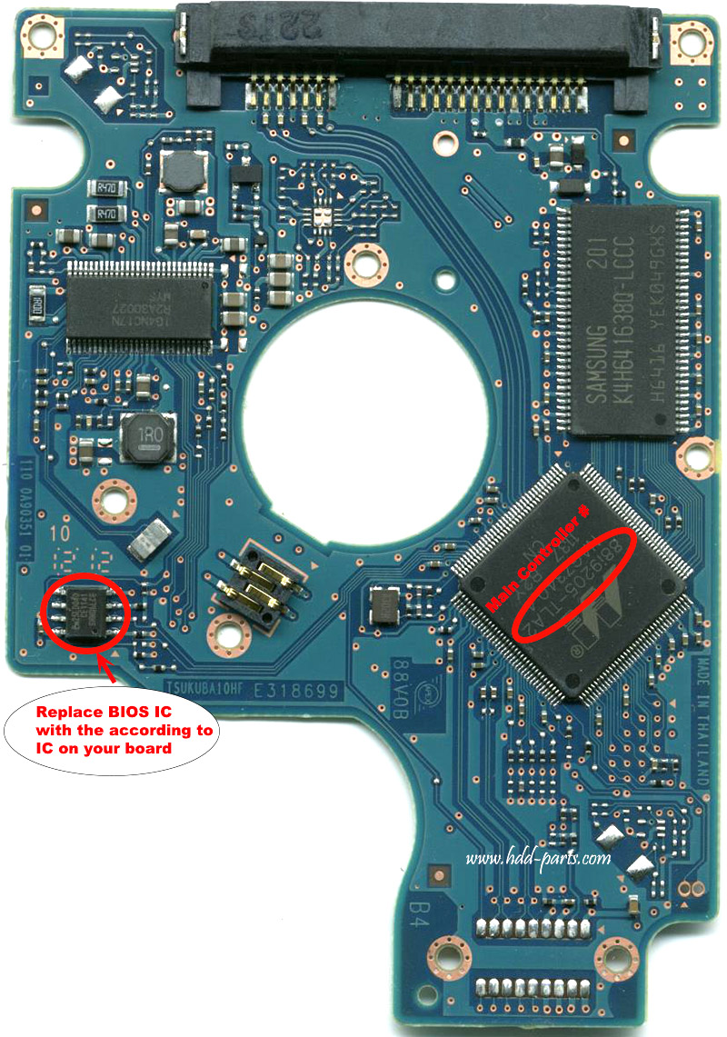
The photo identifies the "BIOS" IC (aka "ROM").
https://www.hdd-parts.com/13022903.html
https://sep.yimg.com/ay/yhst-14437584971410/91711095-6.gif
Measure the voltages at the +5V and +5V(fused) test points. Also measure the resistances of the circled components.
https://www.hdd-parts.com/13022903.html
https://sep.yimg.com/ay/yhst-14437584971410/91711095-6.gif
Measure the voltages at the +5V and +5V(fused) test points. Also measure the resistances of the circled components.
- Attachments
-
Re: over powerd my board, help a numpty out
November 12th, 2018, 22:05
looks like we found a busted fuse
jump it ? can i just solder over the top?
Thanks so much
jump it ? can i just solder over the top?
Thanks so much
- Attachments
-
- diodes_fusessss.jpg (93.24 KiB) Viewed 12217 times
Re: over powerd my board, help a numpty out
November 12th, 2018, 22:52
One of the diodes is shorted. You'll have to remove the TVS diode (the other would a Schottky rectifier). Can you tell us the part markings on each diode? I can see an "R" but nothing else.
Edit: I see that the other is an "A1".
Edit: I see that the other is an "A1".
Last edited by fzabkar on November 12th, 2018, 22:56, edited 1 time in total.
Re: over powerd my board, help a numpty out
November 12th, 2018, 22:55
r and a1
- Attachments
-
Re: over powerd my board, help a numpty out
November 12th, 2018, 22:58
RSA5M, Rohm, TVS diode, 200W, 5V, marking A1:
http://www.rohm.com/web/global/datasheet/RSA5M
http://www.1688eric.com/upload/pdf/2012 ... RSA5MG.pdf
Try removing A1. If the short goes away, then replace the fuse (or bridge it if you feel lucky).
I would test the PCB off the drive. Measure the voltages (V1 - 3) at each of the two inductors (near the TLS2601 motor controller, and the transistor.
- Attachments
-
Last edited by fzabkar on November 12th, 2018, 23:08, edited 1 time in total.
Re: over powerd my board, help a numpty out
November 12th, 2018, 23:06
Sir
You are my hero, ill let you know how it goes
You are my hero, ill let you know how it goes
Re: over powerd my board, help a numpty out
November 13th, 2018, 21:17
fzabkar wrote:The photo identifies the "BIOS" IC (aka "ROM").
https://www.hdd-parts.com/13022903.html
https://sep.yimg.com/ay/yhst-14437584971410/91711095-6.gif
Measure the voltages at the +5V and +5V(fused) test points. Also measure the resistances of the circled components.
Re: over powerd my board, help a numpty out
October 12th, 2019, 18:18
Spildit wrote:Most likely it's better to just replace the PCB with a known good one moving the ROM chip from the bad PCB to the donor compatible PCB.
And pray for the pre-amp to be ok ...
And DO NOT DAMAGE THE ROM CHIP otherwise it's bye-bye data for good ...
Hello! If I have do have the donor PCB and move the BIOS ROM from the damaged one to the donor PCB, do I need any kind of special software or tools to make it work? or will it just work like that? like just connect it the my PC start the data backup?
Greetings!
Re: over powerd my board, help a numpty out
May 20th, 2023, 1:50
fzabkar wrote:RSA5M, Rohm, TVS diode, 200W, 5V, marking A1:
http://www.rohm.com/web/global/datasheet/RSA5M
http://www.1688eric.com/upload/pdf/2012 ... RSA5MG.pdf
Try removing A1. If the short goes away, then replace the fuse (or bridge it if you feel lucky).
I would test the PCB off the drive. Measure the voltages (V1 - 3) at each of the two inductors (near the TLS2601 motor controller, and the transistor.
Dear friend! I accidentally found this topic on the forum, it's been quite a while...
i hope you answer me.
Topic-starter never answered your instruction - measure the voltage at points v1-v3.
I have exactly the same controller and I want to ask you:
What should be the voltage at points b1-b3?
Sincerely, I look forward to your reply.
Re: over powerd my board, help a numpty out
May 20th, 2023, 17:04
@dzonik, what voltages are you seeing at those test points?
Re: over powerd my board, help a numpty out
May 21st, 2023, 10:22
v1- 0,89v
v2- 2,49v
v3 - 5,04v
v2- 2,49v
v3 - 5,04v
Re: over powerd my board, help a numpty out
May 21st, 2023, 10:26
measurements were made without a hermetic block, on only a pcb
Re: over powerd my board, help a numpty out
May 21st, 2023, 12:02
V1 and V2 appear to be consistent with a modern ARM Vcore and Vio.
Re: over powerd my board, help a numpty out
May 21st, 2023, 15:02
Thanks a lot!
It seems to me that I found the reason - this is a combi spindle driver and a magnetic head unit. (also this chip generates a voltage of 2.5 and 0.9 V?)
Chip output to the spindle motor - continuity - 0.78 ohm!
both among themselves and on a common ... Apparently, the output power switches burned out ...
I found a donor board, (all required numbers match)
I ask for advice:
Is it better for me to replace R2A30027 (TLS2601), or is it better to solder the BIOS chip (sop8)?
thanks
Re: over powerd my board, help a numpty out
May 21st, 2023, 15:07
And I also have a question, for my general development  :
:
what kind of chip marked 3260 qfn16?
I couldn't find a datasheet anywhere...
what kind of chip marked 3260 qfn16?
I couldn't find a datasheet anywhere...
Re: over powerd my board, help a numpty out
May 21st, 2023, 15:45
I think most people would recommend transferring the ROM ("BIOS chip"), but be aware that you must not damage this IC.
I don't recognise the "3260" IC, but sometimes these PCBs have a tri-axis accelerometer in that area. That said, your drive has a shock sensor and two rotational vibration sensors, so it would be unusual for it to have an additional accelerometer. But I could be wrong ...
In this PCB that location is unpopulated, which would be consistent with an optional accelerometer:
https://sep.turbifycdn.com/ay/yhst-14437584971410/91711095-6.gif
Also, the presence of all those passive components would suggest the IC has an an analogue section.
Digital accelerometers in 2.5" HDDs:
http://www.hddoracle.com/viewtopic.php?p=19497#p19497
Re: over powerd my board, help a numpty out
May 22nd, 2023, 11:59
Thanks!
Re: over powerd my board, help a numpty out
May 22nd, 2023, 12:01
thanks!
Powered by phpBB © phpBB Group.