https://www.mouser.com/datasheet/2/949/w631gg6kb_a10-2525588.pdf (W631GG6KB, 8M x 8 BANKS x 16 BIT DDR3 SDRAM,
1Gbit)
https://pf.unikeyic.com/datasheet/4c/99/79a3/35/76fa3bb40b98e7c58dc0bccc21ac3995.pdf (W632GG6MB, 16M x 8 BANKS x 16 BIT DDR3 SDRAM,
2Gbit)
The Enable/Fault pin appears to be in a fault state.
Code:
Intermediate Level Input Voltage VI (INT) -- Thermal Fault, Output Disabled -- 0.82V (min) 1.4V (typ) 1.95V (max)
Quote:
The Enable/Fault pin is a tri-state, bi-directional interface. It can be used to enable the output of the device by floating the pin, or disable the chip by pulling it to ground (using an open drain or open collector device). If a thermal fault occurs, the voltage on this pin will go to an intermediate state to signal a monitoring circuit that the device is in thermal shutdown.
Quote:
Thermal protection
When thermal protection is triggered, the output is disabled and the fault line is driven to the middle level. The thermal fault condition is latched, and the part will remain latch off state until restart the power or reset the enable pin.
Quote:
Enable / Fault Pin
The Enable/Fault Pin is a Bi-Directional three levels I/O with a weak pull up current (28uA typical). The three levels are low, mid and high. It functions to enable/disable the part and to relay Fault information.
Enable/Fault pin as an input:
1. Low and mid disable the part.
2. Low, in addition to disabling the part, clears the fault flag.
3. High enables the part (if the fault flag is clear).
Enable/Fault pin as an output:
1. The pull up current may (if not over ridden) allow a “wired nor” pull up to enable the part.
2. An under voltage will cause a low on the Enable/Fault pin, and will clear the fault flag.
3. A thermal fault will cause a mid level on the Enable/Fault pin, and will set the fault flag.
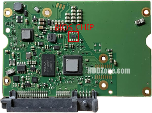
ISTM that both e-fuses have latched off. The only component that is connected to both the 5V and the 12V supplies is the motor controller.


