based on initial diagnosis i suspected the resistor is 50ohm. took apart 2.5" drive and traced the pin to a 50ohm resistor. soldering resistor did not change anything.
remembered the DRAM moved slightly when i was taking off faulty CPU, and a bit of solder came out. quite possible a pin lost contact there.
lifted DRAM chip and indeed there was a pin with hardly a bit of solder on PCB. found pinout, half of the DQ pins to CPU are open. damn i thought either the CPU is faulty or not made good contact. a closer look at datasheet made me realize these are actually x16 chips, not x32. so half of the pins are unused. and indeed DMM check on all DQ0-DQ15 pins showed identical values and all DQ16-DQ32 plus some other x32 specific pins are open. the pin that was missing solder is unused. so nothing wrong here.
reballed DRAM and put back, nothing changes (i was looking if there is something wrong with this since i got the message "configured for UDMA/133 (device error ignored)" while in case where they recovered it with JTAG there was only "configured for UDMA/133")
there was also idea to check crystal, because with damaged CPU there was -3.63V, could this affect crystal stability? i knew after repair i had 0.63V on both crystal pins and 0.92V on nearby test point. meanwhile also flashed initially reconstructed BIOS, with only bad block table additions drive added automatically.
this again resulted in no drive detected in OS, and at this point i checked crystal pins again - one pin is good at 0.63V, another went down 0.48V, also 0.92V test point shows 0.64V. multiple restarts and connecting drive through USB adapter did not change a thing.
next i change BIOS again to the one drive initally tried to reconstruct, and on first boot both crystal pins are good at 0.63V, however 0.92V pin remained at 0.64V - it seems that one of these tables in BIOS contains CPU config register, and with wrong values sets up hw incorrectly.
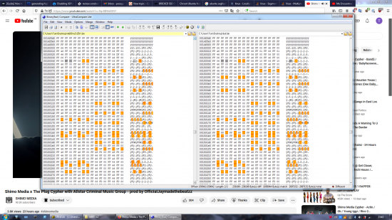
not knowing enough about the BIOS structure i suspect on table at 0x150000, because if i flash dump that would boot drive to "unallocated" state quick, after messing with MU03 loader, this code gets overwritten with same values each time, boot is slow takes several restarts to get the drive detected in disk utility, in general unstable and unpredictable behavior. likely the MU03 loader looked for data at different offset and fooled the CPU somehow
Attachment:
 Untitled.png [ 394.52 KiB | Viewed 184 times ]


