All times are UTC - 5 hours [ DST ]


Post new topic Reply to topic  [ 18 posts ] 
Author Message
 Post subject: Intel SATA SSD 300 (180GB) - Dead - PCB Repair
PostPosted: September 11th, 2023, 16:12 
Offline

Joined: September 11th, 2023, 14:25
Posts: 10
Location: Deutschland
Hello everyone,

while googleing i found this forum where i hopefully find someone who can help me out with my problem. Today my SSD drive died. I rebooted my server and unfortunately my hdd is not showing up anymore. Not being recognized by the bios.

When i plug the hdd in (via usb sata) adapter the only thing getting really hot is the sandforce sf-2281 chip. With continuous power draw of rougly 2.8W.
Was hoping someone here might have some experience with this model. If there are common failures or can help me tracing down the issue.

What i have done so far.
* Visual inspection. Have not found any burned component.
* Searching full short. Have not found a full short to Ground.
* Taking some more or less random measurements
* * In the picture i attached i found two parts of the circuit looking similar.
* * I assumed that the voltage resistance to ground should be the same. This is not the case.
* * Some of the resistors have 20Ohm to Ground on one side and 0Ohm on the other side. While the other similar part has 0Ohm on one side and a way more on the other side.
* * While randomly meassuring capacitors to ground this is similar on other capacitors.

The Voltage in the red marked parts is also different. ~1.08Volt on one part while ~2.8Volt on the other similar part.

Thanks in advance

Attachment:
Board_Top.jpg
Board_Top.jpg [ 3.48 MiB | Viewed 4837 times ]

Attachment:
Board_Bottom.jpg
Board_Bottom.jpg [ 3.27 MiB | Viewed 4837 times ]

Attachment:
Board_Finding_1.jpg
Board_Finding_1.jpg [ 3.58 MiB | Viewed 4837 times ]


Top
 Profile  
 
 Post subject: Re: Intel SATA SSD 300 (180GB) - Dead - PCB Repair
PostPosted: September 11th, 2023, 16:35 
Offline
User avatar

Joined: September 8th, 2009, 18:21
Posts: 15538
Location: Australia
What voltage do you measure at C415 (near L5 in your third photo)?

1.08V is probably the Vcore supply for the controller.

2.8V would be the Vcc supply for the NAND. It seems low, but this reading is consistent with other threads, so it's probably OK.

These are brief specs for the flash:

https://nand.gq/#/decode?pn=JS29F16B08CCME2

I suspect that L5/C415 is probably the Vccq supply for the NAND, either 1.2V or 1.8V.

Can you tell us the marking on U2, U5, U1, U8 and U74?

_________________
A backup a day keeps DR away.


Top
 Profile  
 
 Post subject: Re: Intel SATA SSD 300 (180GB) - Dead - PCB Repair
PostPosted: September 11th, 2023, 17:03 
Offline

Joined: September 11th, 2023, 14:25
Posts: 10
Location: Deutschland
fzabkar wrote:
What voltage do you measure at C415 (near L5 in your third photo)?

1.08V is probably the Vcore supply for the controller.

2.8V would be the Vcc supply for the NAND. It seems low, but this reading is consistent with other threads, so it's probably OK.

These are brief specs for the flash:

https://nand.gq/#/decode?pn=JS29F16B08CCME2

I suspect that L5/C415 is probably the Vccq supply for the NAND, either 1.2V or 1.8V.

Can you tell us the marking on U2, U5, U1, U8 and U74?


Thx for your fast reply.
* The more exact measurements are 1.079V and 2.895V. Took the measurement from the blue marked caps on the third picture.
* Voltage on L5/C415 is 4.978V
* Markings are
* * U1: 35 2V5
* * U8: 8807 8V2D12
* * U2: NFFF
* * U5: D7U231
* * U74: I'm blind. Have not found it on the PCB.


Top
 Profile  
 
 Post subject: Re: Intel SATA SSD 300 (180GB) - Dead - PCB Repair
PostPosted: September 11th, 2023, 17:15 
Offline

Joined: September 11th, 2023, 14:25
Posts: 10
Location: Deutschland
@fzabkar Dont know why my quoted reply does not show up. So another try

* The exact voltage is 1.019 and 2.895 measured on the blue marked caps in the third picture.
* Voltage on C415 (the bigger pad without any component) is showing 4.978V
* The Markings are
* * U1: 35 RV5
* * U8: 8807 8V2D12
* * U2: NFFF
* * U5: D7U231
* * U74: I'm blind. Have not found it on the PCB

Thx for your fast reply.


Top
 Profile  
 
 Post subject: Re: Intel SATA SSD 300 (180GB) - Dead - PCB Repair
PostPosted: September 11th, 2023, 17:39 
Offline
User avatar

Joined: September 8th, 2009, 18:21
Posts: 15538
Location: Australia
I made a mistake with C415. The output voltage should be on C23/C24.

U74 is the SOT23-6 IC at the top left of your second photo.

U1 is a 5V e-fuse.

NIS5135, 3.6A 5V Resettable Electronic Fuse, marking 35:
https://www.onsemi.com/pub/Collateral/NIS5135-D.PDF

MP28258DD, Monolithic Power, 3A, 4.2V - 20V Input, Synchronous Step-down Converter, marking AAA, QFN12:
https://www.monolithicpower.com/pub/media/document/MP28258_r1.14.pdf

_________________
A backup a day keeps DR away.


Top
 Profile  
 
 Post subject: Re: Intel SATA SSD 300 (180GB) - Dead - PCB Repair
PostPosted: September 11th, 2023, 18:05 
Offline
User avatar

Joined: September 8th, 2009, 18:21
Posts: 15538
Location: Australia
APW8807, Anpec, Synchronous Buck Converter, 8A, 6V - 28Vin, marking 8807, TQFN3x3-16A:
https://usermanual.wiki/Document/apw8807ra1anpec.2055995101.pdf

TXS0101DBVR, Texas Instruments, 1-Bit Bidirectional Voltage-Level Shifter for Open-Drain and Push-Pull Application, marking NFFF, SOT-23-6:
https://www.ti.com/lit/gpn/txs0101

_________________
A backup a day keeps DR away.


Top
 Profile  
 
 Post subject: Re: Intel SATA SSD 300 (180GB) - Dead - PCB Repair
PostPosted: September 12th, 2023, 5:29 
Offline

Joined: September 11th, 2023, 14:25
Posts: 10
Location: Deutschland
Hello again. After some Time i have done some investigations and measurements. Btw. i'm not an expert more a bloody beginner and have not much expertise in electronics.
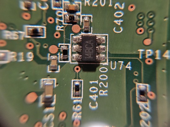
I added some photos and tried to match your sheets to the IC components. I hope this make sense. Also made a photo of the U74.
But to be honest. I Don't know how to continue. Btw. It is normal that the Sandforce chips is getting hot?

* U1: 35 RV5
* * NIS5135, 3.6A 5V Resettable Electronic Fuse, marking 35:
* * https://www.onsemi.com/pub/Collateral/NIS5135-D.PDF
=> I had the idea to check if the enable pin is high. Which seems to be true. Does this make sense?
Attachment:
U1_35.jpg
U1_35.jpg [ 1.81 MiB | Viewed 4713 times ]
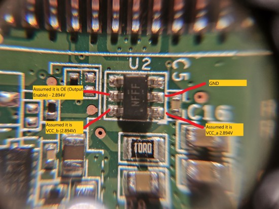

* U2: NFFF
* * TXS0101DBVR, Texas Instruments, 1-Bit Bidirectional Voltage-Level Shifter for Open-Drain and Push-Pull Application, marking NFFF, SOT-23-6:
* * https://www.ti.com/lit/gpn/txs0101
=> I had the idea to check if the enable pin is high. Which seems to be true. Also measured the Voltage of VCC_A and VCC_B which are the same. Does this make sense? I expected that the component is converting signals between A and B while having different voltage levels. But i can also misunderstand the usage of this ic.
Attachment:
U2_NFFF.jpg
U2_NFFF.jpg [ 2.29 MiB | Viewed 4713 times ]
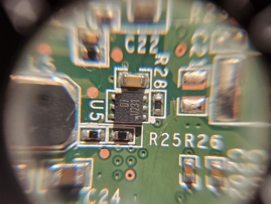

* U5: D7U231
* * MP28258DD, Monolithic Power, 3A, 4.2V - 20V Input, Synchronous Step-down Converter, marking AAA, QFN12:
* * https://www.monolithicpower.com/pub/med ... _r1.14.pdf
=> Here i have no idea. The (amount of) Pins look different.
Attachment:
U5_D7.jpg
U5_D7.jpg [ 2.67 MiB | Viewed 4713 times ]
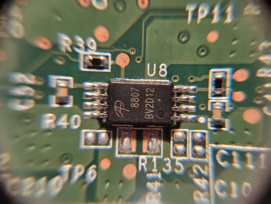
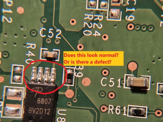

* U8: 8807 8V2D12
* * APW8807, Anpec, Synchronous Buck Converter, 8A, 6V - 28Vin, marking 8807, TQFN3x3-16A:
* * https://usermanual.wiki/Document/apw880 ... 995101.pdf
=> Here i have also no idea. The (amount of) Pins look different.
Attachment:
U8_8807.jpg
U8_8807.jpg [ 2.79 MiB | Viewed 4713 times ]


* U74: I4BCA
Attachment:
U74_I4BCA.jpg
U74_I4BCA.jpg [ 2.8 MiB | Viewed 4713 times ]


I hope this information is helpful. Found soldering joins which don't look very clean. But don't know if this is normal. After that i gave everything a clean with IPA.
Attachment:
Finding_Pins.jpg
Finding_Pins.jpg [ 2.3 MiB | Viewed 4713 times ]


Top
 Profile  
 
 Post subject: Re: Intel SATA SSD 300 (180GB) - Dead - PCB Repair
PostPosted: September 12th, 2023, 5:45 
Offline

Joined: September 11th, 2023, 14:25
Posts: 10
Location: Deutschland
Forgot to mention. The Voltage on Both C23/C24 is 2.894V


Top
 Profile  
 
 Post subject: Re: Intel SATA SSD 300 (180GB) - Dead - PCB Repair
PostPosted: September 12th, 2023, 10:36 
Offline

Joined: September 11th, 2023, 14:25
Posts: 10
Location: Deutschland
Can not edit posts. I Hope this is not getting confusion. I Made measurments of the rest.
Attachment:
U5_D7.jpg
U5_D7.jpg [ 1.9 MiB | Viewed 4613 times ]

Attachment:
U8_8807.jpg
U8_8807.jpg [ 1.97 MiB | Viewed 4613 times ]

Attachment:
U74_I4BCA.jpg
U74_I4BCA.jpg [ 2.03 MiB | Viewed 4613 times ]


Top
 Profile  
 
 Post subject: Re: Intel SATA SSD 300 (180GB) - Dead - PCB Repair
PostPosted: September 12th, 2023, 14:50 
Offline
User avatar

Joined: September 8th, 2009, 18:21
Posts: 15538
Location: Australia
Very sorry, I incorrectly identified the 8807 IC. It's actually an AO8807, and it is configured as a dual load switch. As such, it is working correctly.

AO8807, Alpha & Omega, Dual P-Channel Enhancement Mode MOSFET, -12V, -6.5A, 20mOhm RDSon, marking 8807, TSSOP-8:
https://www.datasheetarchive.com/datasheet?id=fb759cdd1383c567d3011c619420043479d935

"D7" is a step-down converter. It is producing 1.8V, as expected.

The 5V e-fuse is working correctly.

In short, the 3 power supplies are OK.


MP6400DJ-01, adjustable Programmable-Delay Supervisory Circuit, marking 4Bxx, TSOT23-6:
https://www.monolithicpower.com/en/documentview/productdocument/index/version/2/document_type/Datasheet/lang/en/sku/MP6400/

_________________
A backup a day keeps DR away.


Top
 Profile  
 
 Post subject: Re: Intel SATA SSD 300 (180GB) - Dead - PCB Repair
PostPosted: September 12th, 2023, 16:32 
Offline
User avatar

Joined: September 8th, 2009, 18:21
Posts: 15538
Location: Australia
RT8010-12PQW, Richtek, High Efficiency PWM Step-Down DC/DC Converter, 1.5MHz, 1A, 2.5V - 5.5Vin, marking D7, WDFN-2x2-6L:
https://www.richtek.com/assets/product_file/RT8010=RT8010A/DS8010A-12.pdf

_________________
A backup a day keeps DR away.


Top
 Profile  
 
 Post subject: Re: Intel SATA SSD 300 (180GB) - Dead - PCB Repair
PostPosted: September 17th, 2023, 6:26 
Offline

Joined: September 11th, 2023, 14:25
Posts: 10
Location: Deutschland
@fzabkar thx for providing me your help. Really appreciate that. Several hours later i ended up with that. I made several measurements and tried to understand what is happening... (see pics)
Do you have an idea if I4BCA is working and maybe can provide me support of further investigation? I don't know whats going on. Sense looks low. But don't know if this is ok.
I know it's your time you spend and i don't have a lot of knowledge. So really appreciate that. Thx a lot.

Attachment:
U5_IC_From_Documentation.jpg
U5_IC_From_Documentation.jpg [ 156.96 KiB | Viewed 4287 times ]

Attachment:
U74_IC_From_Documentation.JPG
U74_IC_From_Documentation.JPG [ 732.5 KiB | Viewed 4287 times ]

Attachment:
U74_Tracing.jpg
U74_Tracing.jpg [ 2.7 MiB | Viewed 4287 times ]


Top
 Profile  
 
 Post subject: Re: Intel SATA SSD 300 (180GB) - Dead - PCB Repair
PostPosted: September 17th, 2023, 7:48 
Offline

Joined: September 11th, 2023, 14:25
Posts: 10
Location: Deutschland
Edit: In addition to the posting directly above

I still can't get it out of my head why this logical level shifter (see U2: NFFF) have the same VCC_a and VCC_b voltage. And also have continuity between. When reading the documention https://www.ti.com/lit/ds/symlink/txs01 ... 4874203563 i guess the voltage should be different. In my head it makes no sense to have a voltage shifter if the voltage of the components is the same. Dead ic?


Top
 Profile  
 
 Post subject: Re: Intel SATA SSD 300 (180GB) - Dead - PCB Repair
PostPosted: September 17th, 2023, 15:51 
Offline
User avatar

Joined: September 8th, 2009, 18:21
Posts: 15538
Location: Australia
4BCA is working correctly. The sensed voltage (0.48V) is greater than the internal reference (0.4V), so the Reset pin should be inactive (high).

All the switchmode regulators are producing the correct output.

The function of U2 is puzzling to me as well. Is there continuity between Vcca and Vccb?

That said, the usual problem with SandForce based SSDs is firmware related. I expect that the controller has panicked after encountering bad NAND or a bad firmware module, and the SSD is now in a BSY state.

I'm not sure, but I expect that J3 may be the "ROM mode" shorting pads and J1 may be the UART port. If the SSD identifies itself in ROM mode, this would be a good sign that the controller has basic sanity.

_________________
A backup a day keeps DR away.


Top
 Profile  
 
 Post subject: Re: Intel SATA SSD 300 (180GB) - Dead - PCB Repair
PostPosted: September 17th, 2023, 17:29 
Offline

Joined: September 11th, 2023, 14:25
Posts: 10
Location: Deutschland
There is Zero Ohm continuity between Vcca and Vccb. Thought about desoldering (U2: NFFF) and take measurments on the pads.

Found an article about how to unbick the chip https://computerlounge.it/how-to-unbrick-sandforce-ssd/ .They talk about shorting "J5" which optically looks similar to "J3" you mentioned. Is there a way to double check if "J3" is right for shorting?

I'll see which of this two thing i try next. Unfortunatly i have to do a lot of other stuff this week.
If you have further hints i would be happy. Thanks a lot!


Top
 Profile  
 
 Post subject: Re: Intel SATA SSD 300 (180GB) - Dead - PCB Repair
PostPosted: September 17th, 2023, 18:34 
Offline
User avatar

Joined: September 8th, 2009, 18:21
Posts: 15538
Location: Australia
One pad of J3 is probably connected to ground. The other pad appears to be pulled up to Vio via a resistor. If so, then it would be electrically safe to short these pads.

_________________
A backup a day keeps DR away.


Top
 Profile  
 
 Post subject: Re: Intel SATA SSD 300 (180GB) - Dead - PCB Repair
PostPosted: September 24th, 2023, 4:56 
Offline

Joined: September 11th, 2023, 14:25
Posts: 10
Location: Deutschland
It's finally working again. First of all thank you a lot for your support.

I started with shorting the two pins on J3. After that it showed up in bios again. After going through all the steps of the tutorial it's fully functional again.

Also measured (U2: NFFF) again because it caused me headache. It still has the same voltage on VCC_a and VCC_b. This might help someone in the future with similar problems.

One question i already had in mind during the whole conversation.
How are you able to identify the ICs only by the markings? I googled a while but have not found anything helpful.


Top
 Profile  
 
 Post subject: Re: Intel SATA SSD 300 (180GB) - Dead - PCB Repair
PostPosted: September 24th, 2023, 13:04 
Offline
User avatar

Joined: September 8th, 2009, 18:21
Posts: 15538
Location: Australia
This is now my primary resource for part marking info:

http://markingcodes.com/search/c/35
http://markingcodes.com/search/c/nfff

_________________
A backup a day keeps DR away.


Top
 Profile  
 
Display posts from previous:  Sort by  
Post new topic Reply to topic  [ 18 posts ] 

All times are UTC - 5 hours [ DST ]


Who is online

Users browsing this forum: No registered users and 106 guests


You cannot post new topics in this forum
You cannot reply to topics in this forum
You cannot edit your posts in this forum
You cannot delete your posts in this forum
You cannot post attachments in this forum

Search for:
Jump to:  
Powered by phpBB © 2000, 2002, 2005, 2007 phpBB Group