The self-developed LDPC error correction engine of NFT has completed full-process integrated development and entered the final stage of performance tuning and multi-scenario stress testing.
This functional upgrade is fully compatible with the existing operation workflow.
Users do not need to adjust their original operating habits to complete data correction for images adopting the LDPC verification architecture.
It greatly makes up for the shortcomings of the BCH algorithm in data recovery scenarios that require LDPC error correction.
Once all comprehensive testing and performance optimization are finished, the LDPC data correction module will be officially launched.
We will simultaneously expand the compatible Model template library to support more mainstream storage device models.
Stay tuned!
Reference operation demonstration videos:
https://youtu.be/gJvhb_a12Wchttps://youtu.be/D36ngA6f0wgProcessing results for YS9082:
Attachment:
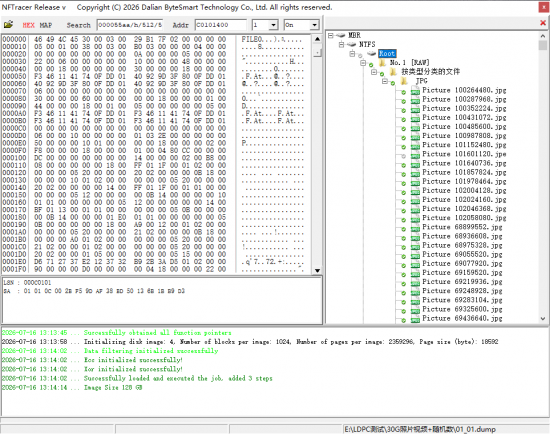 1.png [ 81.65 KiB | Viewed 6402 times ]
Explanation on Continuous Expansion of Supported Models:
Only partial LDPC algorithms and sorting algorithms are supported in the initial official release. If you encounter unsupported LDPC architectures, new BCH structures or Layouts during practical operations, please contact us.
Simple Layouts can be added on the same day. For complex cases, submit the following information and data to our technical team. We will conduct underlying data analysis immediately, iteratively develop matching LDPC/BCH decoding algorithms, Layouts and Model templates, and continuously expand the tool’s compatibility coverage:
1. Clear hardware photos
2. Controller model and chip ID (if known)
3. Data of several erase blocks, or a complete full dump
4. XOR file (if available)
5. For new schemes/chipsets without an existing XOR file, two separate images are required:
Image 1: Read image captured after writing LBA data to the identical controller ID chip
Image 2: Generate a 3GB file filled entirely with 00s and another filled entirely with 77s, then write both to a healthy drive. The all-zero file only needs to account for 5%–10% of the total image size.
For multi-chip devices, capture a separate image for each chip. If the full dump file is excessively large, you may intercept partial valid data (note this may reduce analysis accuracy).
If the full image size is too big, you can write LBA data first, format the media, then import the all-00 and all-77 test files for extraction.



 FAQ
FAQ Search
 Login
Login Register
 HDDGURU FILES
