Hitachi 2.5" HDD #13G1583-other HDD part #s in body of post
April 25th, 2010, 23:24
Hello,
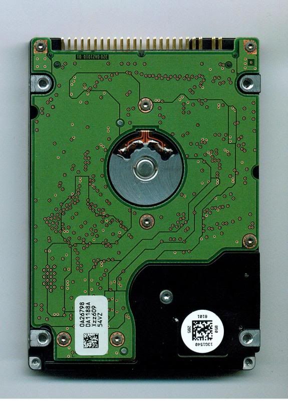
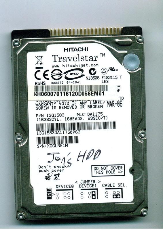
I have a Hitachi HDD, #13G1583, MLC# DL1175, serial XGGLNE1M, board part number 0A26798 Da1188A Xzz609 54VZ.
Basically, I removed this from a notebook in order to do a backup (oh, the irony, as you'll see). It was working fine just before this. It was getting pretty full and I needed to clone it to a larger HDD. For some reason immediately after this, I could not get it to read in the desktop where I do cloning, and no enclosure would see it either. I tried every jumper setting on my 2.5" to 3.5" adapters after this and tested known good drives with every adapter and enclosure I have (the known goods were fine). Frustrated that this drive wouldn't be seen in anything, I finally put the drive back in the notebook thinking, "Well it worked in there, I'll just put it back and see if I can just get an image from there", and then nothing. The notebook acts the same whether there is no drive there or if the drive is installed. No sound from the drive, no spinning, just nothing.
So, I'm hoping someone has this board available, but I'm definitely wanting to hear your professional opinions on whether you think this is what's needed, as I have almost no experience with board swapping.
Also, maybe some insight into what might have went wrong would be great. I'm really stumped as to what could have happened there.
Hope you can help and I very much appreciate all you might be able to offer.
Thanks very much!
-Rob
Re: Hitachi 2.5" HDD #13G1583-other HDD part #s in body of post
April 25th, 2010, 23:59
Sorry I had to add a second post. For some reason, I could not edit. Here's some pics of the drive.

-Rob
-Rob
Re: Hitachi 2.5" HDD #13G1583-other HDD part #s in body of post
April 26th, 2010, 1:04
My apologies, I attached the wrong pics. Here are the correct ones.
-Rob
-Rob
Re: Hitachi 2.5" HDD #13G1583-other HDD part #s in body of post
April 26th, 2010, 3:02
Hitachi notebook drives are not interchangeable, they have pretty-much unique info programmed into the PCB.
Re: Hitachi 2.5" HDD #13G1583-other HDD part #s in body of post
April 26th, 2010, 12:00
pcimage wrote:Hitachi notebook drives are not interchangeable, they have pretty-much unique info programmed into the PCB.
I see. That is worrying. Any tips how I might proceed with recovery on this drive?
Thanks again!
-Rob
Re: Hitachi 2.5" HDD #13G1583-other HDD part #s in body of post
April 26th, 2010, 16:55
Well, the best way would be to seek pro help, it should be pretty cheap if it's "just" a PCB problem.
Or you could get a compatible PCB and transfer the NVRAM chip, but it's very tiny and if you mess it up it turns a $150 recovery into a $1,500 recovery instantly.
Or you could get a compatible PCB and transfer the NVRAM chip, but it's very tiny and if you mess it up it turns a $150 recovery into a $1,500 recovery instantly.
Re: Hitachi 2.5" HDD #13G1583-other HDD part #s in body of post
April 26th, 2010, 20:21
pcimage wrote:Or you could get a compatible PCB and transfer the NVRAM chip, but it's very tiny and if you mess it up it turns a $150 recovery into a $1,500 recovery instantly.
agree. i have 0A26797 Da1188A in stock.
Re: Hitachi 2.5" HDD #13G1583-other HDD part #s in body of post
April 26th, 2010, 20:58
Ok, gotcha. Since these boards are SUPER thin, I'd hate to overheat it and ruin the board/NVRAM. What kind of ballpark price range (should I assume "range" is the key word?) should one pay for a pro to fix it if it is "just" a board issue? I'm sure I could do it, I just would hate to screw it up, since my soldering skills are merely OK.
Thanks again, folks!
-Rob
Thanks again, folks!
-Rob
Re: Hitachi 2.5" HDD #13G1583-other HDD part #s in body of post
April 27th, 2010, 0:26
rbudrick wrote:0A26798
Hi, we have this working PCB in stock, pls contact my hotmail.
Thanks
Eric
Re: Hitachi 2.5" HDD #13G1583-other HDD part #s in body of post
April 28th, 2010, 19:21
rbudrick wrote:Ok, gotcha. Since these boards are SUPER thin, I'd hate to overheat it and ruin the board/NVRAM. What kind of ballpark price range (should I assume "range" is the key word?) should one pay for a pro to fix it if it is "just" a board issue? I'm sure I could do it, I just would hate to screw it up, since my soldering skills are merely OK.
Thanks again, folks!
-Rob
hi,
i can help you replace it. please contact me by email or MSN.
Re: Hitachi 2.5" HDD #13G1583-other HDD part #s in body of post
May 10th, 2010, 2:24
Hello,
My wife and I haven't yet decided what to do with this drive yet, but just for curiosity's sake, since I finally got the correct size screwdriver bit to see the component side of this PCB (I had to at least know if something burnt out, and I don't see anything), what IC would I actually be taking from this and replacing onto a donor PCB? If it is indeed the PCB at fault, is this most likely all I'd have to do is swap the IC?
I'm a bit worried because they are all surface mounts, with only one little 8-pin IC even solderable with very specialized tools.
Edit: OK, I see 2 small 6-pin ICs too.
-Rob
Re: Hitachi 2.5" HDD #13G1583-other HDD part #s in body of post
May 10th, 2010, 2:37
1-U6
2-You have to search for TVS also, your PCB looks fine with no visible damage.
Good luck
2-You have to search for TVS also, your PCB looks fine with no visible damage.
Good luck
Re: Hitachi 2.5" HDD #13G1583-other HDD part #s in body of post
May 10th, 2010, 20:46
unknown20010 wrote:1-U6
2-You have to search for TVS also, your PCB looks fine with no visible damage.
Good luck
Thanks, unknown20010! Sorry if this sounds like a newb question, but what is TVS?
Is this it?:
http://en.wikipedia.org/wiki/Transient_ ... suppressor
If so, I'm still not sure where I'd find one or what it would look like.
Thanks!
-Rob
Re: Hitachi 2.5" HDD #13G1583-other HDD part #s in body of post
May 11th, 2010, 6:30
rbudrick wrote:Thanks, unknown20010! Sorry if this sounds like a newb question, but what is TVS?
Is this it?:
http://en.wikipedia.org/wiki/Transient_ ... suppressor
Yes.
rbudrick wrote:If so, I'm still not sure where I'd find one or what it would look like.
Re: Hitachi 2.5" HDD #13G1583-other HDD part #s in body of post
May 12th, 2010, 1:41
I believe the arrow in the top RH corner is pointing to F1 which is probably a 2A fuse (does it have an "N" marking?).
The TVS diode is probably the horizontally mounted device just below it.
The TVS diode is probably the horizontally mounted device just below it.
Re: Hitachi 2.5" HDD #13G1583-other HDD part #s in body of post
May 17th, 2010, 0:31

Yes, F1 does have a N on it. On the TVC, it looks like there's a 000 on it. Is this the one you are referring to?
Pardon my newb questions, but why would this need to be replaced too?
Thanks very much again!
-Rob
Re: Hitachi 2.5" HDD #13G1583-other HDD part #s in body of post
May 17th, 2010, 4:12
The SMD with N (Blue) is the fuse. Just below that is a Zero Ohm link (digits 0000 (Black)) and below that is probably the TVS (Brown) SMD. Check all 3 components
Re: Hitachi 2.5" HDD #13G1583-other HDD part #s in body of post
May 17th, 2010, 5:08
The brown SMD part appears to be a capacitor. If it were a TVS diode, it would be unidirectional, which means it would have some kind of polarity indicator, ie a stripe at one end.
I suspect that your board doesn't have any diode protection.
In any case I would measure the resistance of the brown component. It will at least tell you whether there is a short on the PCB. If a short does exist, then I would expect it to involve the motor control chip at U5 (TLSxxxx ???). Hopefully the other major components were protected by their respective stepdown regulated supplies.
Re: Hitachi 2.5" HDD #13G1583-other HDD part #s in body of post
May 17th, 2010, 6:01
@
rbudrick the brown cap is a bypass cap which is typicaly used to regulate the power. Basic idea is that it smooths out the supply to the electronics. So technicaly it's not a TVS.
As I have seen in the past "some" people connect the 2.5" adapter the wrong way round and kill the interface electronics (sending 5v down the interface pins)
Re: Hitachi 2.5" HDD #13G1583-other HDD part #s in body of post
May 17th, 2010, 9:50
@ rbudrick
You have to plug your drive and listen carefuly for any strange sounds.
I think the problem elsewhere not the PCB. Maybe heads stuck to platters ?
You have to plug your drive and listen carefuly for any strange sounds.
I think the problem elsewhere not the PCB. Maybe heads stuck to platters ?
Powered by phpBB © phpBB Group.