MultiDrive – free backup, clone & wipe disk utility from Atola Technology

All times are UTC - 5 hours [ DST ]


Post new topic Reply to topic  [ 2 posts ] 
Author Message
 Post subject: 1TB My Passport 2.5" - Burnt component on the PCB
PostPosted: November 28th, 2012, 1:31 
Offline

Joined: March 24th, 2011, 0:18
Posts: 182
Location: Australia
Hi Guys,

I got a 1TB My Passport 2.5" with usb 3.0 interface.

The drive is not spinning at all.
The customer said that he connected it to some PCI-EXP card and applied power and then it happened.
It seems like one or more PCB components are fried, similar to the TV's on a 3.5".

When i opened it up, there was a single burn mark on the Gray sponge attached to the PCB from the internal side.
If you look at the attached images, it was somewhere in the PCB-Internal.img inside the area marked with red but i can't say exactly which component.

Does these drives has TV's diodes?
What other components on these drives may fail usually because of wrong voltage.

Thanks,
Oded


Attachments:
PCB-Internal.jpg
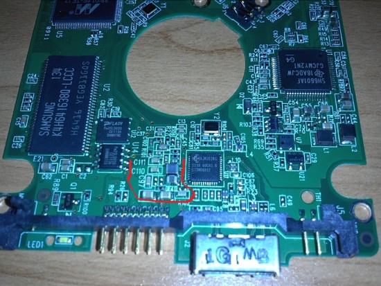
PCB-Internal.jpg [ 336.79 KiB | Viewed 4401 times ]
PCB-external.jpg
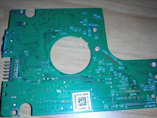
PCB-external.jpg [ 294.27 KiB | Viewed 4401 times ]
Front-Sticker.jpg
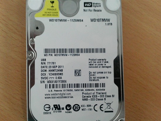
Front-Sticker.jpg [ 237.51 KiB | Viewed 4401 times ]
Top
 Profile  
 
 Post subject: Re: 1TB My Passport 2.5" - Burnt component on the PCB
PostPosted: November 28th, 2012, 3:16 
Offline
User avatar

Joined: September 8th, 2009, 18:21
Posts: 16954
Location: Australia
I would think that those components in the red area would form part of a 1.2V switchmode Vcore supply for the JMS538S bridge IC. Capacitors don't normally produce any heat, so I would suspect that one of the resistors may have cooked. There could be a current sense resistor (Rnn) but I can't make out anything other than R41 or perhaps R10.

The voltages at coils L1 and L2 near the SH6601AF motor controller would probably be the Vcore and Vio supplies for the Marvell MCU. You could also measure the voltages on pin #8 of each of the flash memories at U12 and U14 (either +2.5V or +3.3V). The voltage on pin #1 of the SDRAM should be +2.5V.

I presume you would backup U12 and U14 before applying power.

As for a TVS diode or fuse, I can't recognise anything that would fit the bill.

_________________
A backup a day keeps DR away.


Top
 Profile  
 
Display posts from previous:  Sort by  
Post new topic Reply to topic  [ 2 posts ] 

All times are UTC - 5 hours [ DST ]


Who is online

Users browsing this forum: No registered users and 31 guests


You cannot post new topics in this forum
You cannot reply to topics in this forum
You cannot edit your posts in this forum
You cannot delete your posts in this forum
You cannot post attachments in this forum

Search for:
Jump to:  
Powered by phpBB © 2000, 2002, 2005, 2007 phpBB Group