fzabkar wrote:
Can you tell us the markings on U5 in the second photo (near the SATA power connector)? I expect this is a MOSFET, in which case it would be the next component to be clobbered after the TVS diode.
It's extremely hard to read for me, but I think it says 1D Wxx (The X's are characters I cannot read)
fzabkar wrote:
The diode is the one with the Littelfuse logo (LF + AG + OE). Is this diode shorted?
I tested with my multimeter, with the black probe on the line side and got no beeps. Switching to OHMS mode, and it shows 6.0ohms but slowly went up over time exceeding 8 ohms
fzabkar wrote:
Can you tell us the markings on the 9040VMxxx chip in the first photo? It looks cooked.
It looks like leftover flux or something, though the gunk feels pretty solid. The markings on this are as follows:
9040VW509
U000Z2
170345
fzabkar wrote:
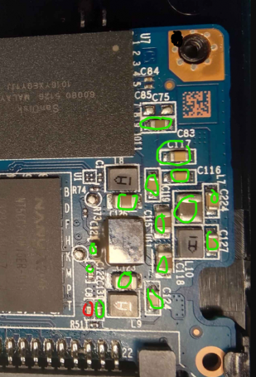
Can you measure the resistance between each of the inductors and ground (L7, L8, L9, L10)? L7 is the larger component under L10.
[/quote]
L7 - All inductors have solid beeps
L8 - All inductors have solid beeps
L9 - One inductor is not beeping on either side and it's marked in the picture below
L10 - All inductors have solid beeps
The black dot in the image is where I put my black probe for ground and I used the Red probe on all of the inductors on both sides. Let me know if I missed anything..
Attachment:
 Screenshot 2024-07-30 100508.png [ 499.85 KiB | Viewed 7532 times ]